
Adding and Configuring Components

Upgrades and Add-ons
Installing a 12-Slot Peripheral Component Interconnect
(PCI) Chassis - Offline
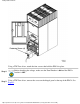
The 12-slot card cage may be installed into almost any available I/O bay within a powered off target
cabinet. Chassis or card cage power is off when no card cage is installed.
Card cage addition is less complicated than replacement, because fewer steps are needed. Be sure to
follow all the steps listed to ensure successful operation.
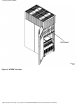
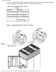
PCI Chassis Locations Within The SD 32 Way Cabinet
There are 4 spaces available for 12-slot card cage, on the pair of master I/O backplanes within a
Superdome 32-Way cabinet (two spaces in the front and two spaces in the rear).
PCI Chassis Locations Within The I/O Expansion Cabinet
There are 2 spaces available for 12-slot card cages, on the single master I/O backplane per I/O Chassis
Enclosure (ICE) assembly within an I/O expansion cabinet. However, there may be up to three ICE
assemblies within an I/O expansion cabinet.
Initial (Offline) Addition Procedure
This procedure must be followed prior to adding a 12-slot card cage, while the target cabinet is powered
off:
Step 1.
Visually inspect the target PCI chassis for the proper part number and revision. This will help
ensure part quality.
Step 2.
Make proper Electrostatic Discharge (ESD) connections to the target master I/O backplane,
and perform a daily ESD selftest. [refer to nugget]
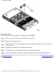
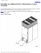
Step 3. Install the PCI card cage in the target I/O bay and chassis slot of the master I/O backplane.
Step 4.
Install the pair of Ring I/O Adapter (REO) Link cable bundles between the target cell and the
target master I/O backplane, within the target cabinet.
Step 5. Go directly to: "Final (Offline) Addition Procedure."
Final (Offline) Addition Procedure
This section contains information on verifying the installation of both the REO link cables and the target
PCI chassis:
Installing a PCI Chassis - Offline
http://superdome-test.fc.hp.com/sd_web/content/00/00/H4/idd/405.html (1 of 2) [03/01/2001 2:10:33 PM]