
Adding and Configuring Components

Step 4.
Attach the green and yellow ground cable. Use the hardware that was retained during the cable
removal.
Step 5.
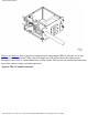
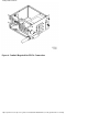
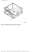
Replace the bottom panel on the PDCA. Use the five screws retained from the removal
procedure. Refer to Figure 12 for panel installation details.
Step 6.
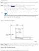
To verify the proper wiring to a four-wire PDCA, use a DVM to measure the voltage at the test
points. Voltage should read 200 - 240 Vac phase to phase as measured between the test points
as follows: L1 to L2, L2 to L3, L1 to L3.
In some electrical distributions around the world, it is possible to measure 415 VAC
phase to phase.
To verify the proper wiring to a five-wire PDCA, use a DVM to measure the voltage at the test
points. Voltage should read 200 - 240 Vac phase to neutral, as measured between the test
points as follows: L1 to N, L2 to N, L3 to N.
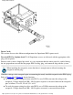
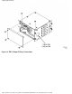
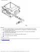
Figure 14
Cable Preparation Detail
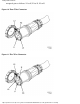
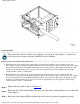
Figure 8 and Figure 9 detail a suggested configuration for connecting the PDCA when the use of rigid conduit is required
or desired. Using a 4 inch nipple and a 90o elbow allows the conduit to pass through the raised floor at a point immediately
past the cabinet. This prevents the conduit from extending beyond the cabinet creating a possible trip hazard.
Figure 15 PDCA Conduit Connection
Adding additional PDCAs
http://superdome-test.fc.hp.com/sd_web/content/00/0C/0P/idd/406.html (20 of 22) [03/01/2001 2:11:03 PM]