
Adding and Configuring Components


are large and easily damaged.
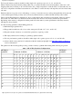
Example 1 Incorrect Memory Distribution Across Partitions
If a two cell partition has 2 Gbytes of memory on one cell and 16 Gbytes on another, 4 Gbytes will be
interleaved (two from each cell) and 14 Gbytes will be assigned to one cell only. This results in inconsistent
bandwidth and latency problems.
For more details on memory configuration see Overview: Memory. For detailed instructions on how to remove
and replace DIMMs see Replacing a DIMM.
Preliminary Procedures This procedure must be completed prior to installing the new cell board.
Step 1. Visually inspect the new part for proper part number and revision.
Step 2.
Using your add-on configuration as a guide determine which cell boards must be removed to have
their DIMMs redistributed.
Step 3.
Verify the cabinet number(s) using the front and rear panel displays. The displays show a numeric
cabinet value and are located on the Superdome front and rear door assemblies.
Step 4. Prepare a electrostatic discharge (ESD) safe work surface and make proper ESD connections.
Step 5. Shutdown the target partition in an orderly manner.
Step 6. Open the front cabinet door using the latch located on the right side of the front door.
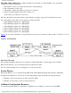
Removing Cell Boards For each cell requiring removal, complete the following steps:
Remove +48 V power from the target cell board using the pe command on the GSP.
You may have to power off +48 V power to all FRUs within the target cabinet.
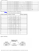
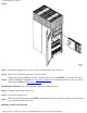
Figure 2 Removing a Cell Board
Installing Additional Cell Boards
http://superdome-test.fc.hp.com/sd_web/content/00/0A/DV/idd/401.html (3 of 6) [03/01/2001 2:09:45 PM]