Superdome Site Preparation Guide HP 9000 Systems Eighth Edition Manufacturing Part Number: A5201-10024 80602 USA © Copyright 2002 Eighth Edition June 2002
Legal Notices The information in this document is subject to change without notice. Hewlett-Packard makes no warranty of any kind with regard to this manual, including, but not limited to, the implied warranties of merchantability and fitness for a particular purpose. Hewlett-Packard shall not be held liable for errors contained herein or direct, indirect, special, incidental or consequential damages in connection with the furnishing, performance, or use of this material. Restricted Rights Legend.
Contents 1. System Specifications General . . . . . . . . . . . . . . . . . . . . . . . . . . . . . . . . . . . . . . . . . . . . . . . . . . . . . . . . . . . . . . . . . . . . . . . . . . . . . 3 Server System . . . . . . . . . . . . . . . . . . . . . . . . . . . . . . . . . . . . . . . . . . . . . . . . . . . . . . . . . . . . . . . . . . . . . . . 4 Basic System Building Blocks . . . . . . . . . . . . . . . . . . . . . . . . . . . . . . . . . . . . . . . . . . . . . . . . . . . . . . . . .
Contents 3. Facility Guidelines Facility Characteristics . . . . . . . . . . . . . . . . . . . . . . . . . . . . . . . . . . . . . . . . . . . . . . . . . . . . . . . . . . . . . . . Floor Loading . . . . . . . . . . . . . . . . . . . . . . . . . . . . . . . . . . . . . . . . . . . . . . . . . . . . . . . . . . . . . . . . . . . . . Windows . . . . . . . . . . . . . . . . . . . . . . . . . . . . . . . . . . . . . . . . . . . . . . . . . . . . . . . . . . . . . . . . . . . . . . . . . Space Requirements. . .
Preface v
Revision History Table 1 Revision Revisions After May 2001 Part Number Eighth Release Date June 2002 Description Added recommendations for the in-line connector and the wall panel receptacle that are supplied by the end user (customer). These parts are not provided by H.P. due to the extensive options available for the cusomter’s building wiring infrastructure. Added miscellaneous updates and corrections. Seventh A5201-10023 November 2001 Added new PDCA options.
Safety and Regulatory Information For your protection, this product has been tested to various national and international regulations and standards. The scope of this regulatory testing includes electrical/mechanical safety, radio frequency interference, acoustics, and know hazardous materials.Where applicable, approvals obtained from third-party test agencies are shown on the product label.
WARNING Use care when lifting a cell board. Each cell board can weigh as much as 48 pounds (22kg). WARNING Use care when working with hazardous voltages. This equipment may be configured with dual input line sources. Hazardous voltages and energy maybe present even after the removal of a single input source. Trained service personnel must follow the service guidelines. WARNING Do not stand in front of the equipment as it is rolled off the pallet onto the ramps.
The user is cautioned that changes or modifications not expressly approved by Hewlett-Packard could result in the equipment being noncompliant with FCC Class A requirements and void the user’s authority to operated the equipment. Japanese Radio Frequency Interference VCCI This equipment is in the Class A category information technology equipment based on the rules of Voluntary Control Council For Interference by Information Technology Equipment (VCCI).
• CCCC: registration number Figure 3 Korean RFI Translation Class A Equipment: Please note that this equipment has been approved for business purpose with regards to electromagnetic interference, if purchased un error for use in residential area, you may wish to exchange the equipment where you purchase it. Class B Equipment: Please note that this equipment has been approved for non-business with regards to electromagnetic interference.
BSMI (Taiwan Areas) This product is fully compliant to CNS 13438 (CISPR 22: 1993) Class A. The EMC label is in the form shown in Figure 4. The eight # signs represent an eight-character, alpha-number string. Figure 4 Figure 5 Acoustics (Germany) Acoustic Noise (A-weighted Sound Pressure Level LpA) measured at the bystander position, normal operation, to ISO 7779: LpA = 65.1 dB.
Install a PE (protective earthing) conductor that is identical in size, insulation material, and thickness to the branch-circuit supply conductors. The PE conductor insulation must be green with yellow stripes. The earthing conductor is to be connected from the unit to the building installation earth or, if supplied by a separately derived system, at the supply transformer or motor-generator set grounding point.
Table 4 WARNING Wall Disconnect Device Circuit Breaker Specification (Continued) Circuit Interruption Simultaneous trip of all poles Ground The protective earth (PE) ground wire is not switched Provide a disconnect device to protect against abnormal hazards. Systems configured with a full complement of cells, memory, and I/O and connected to a 5-wire source must have a maximum 24A 3-phase with neutral (4-pole) circuit breaker installed as part of the building installation.
WARNING If the system has two PDCA installed, ensure that power is removed from both PDCA before removing fuses. Fuse Warnings Superdome Only: WARNING Disconnect power before changing fuse. CAUTION For continued protection against risk of fire, replace fuses only with same type and rating. Lithium Battery Caution WARNING Observe the correct polarity when changing the lithium battery. There is a danger of explosion if battery is installed incorrectly.
International Symbols (IEC335-1) Figure 7 Four Wire Connection Figure 8 Five Wire Connection Associated Documents The following documents provide more details on the topics presented in this manual: • Standard for the Protection of Electronic Computer Data Processing Equipment, (NFPA75) National Fire Protection Association • EIA Standard RS-232-C, Electronic Industries Association • Electrostatic Discharge Failures of Semiconductor Devices, Unger, B.A.
Figure 9 xvi Superdome Declaration of Conformity Page 1
Figure 10 Superdome Declaration of Conformity Page 2 xvii
Figure 11 xviii I/O Expansion Cabinet Declaration of Conformity Page 1
Figure 12 I/O Expansion Cabinet Declaration of Conformity Page 2 xix
xx
1 System Specifications The following Superdome specifications are based on HP Environmental Class C2. Class C2 is a controlled computer room environment where products are subject only to controlled temperature and humidity extremes.
System Specifications • “Server System” on page 4 describes the basic system building blocks. • “Upgrading Superdomes and Server Systems” on page 9 discusses the additional requirements resulting from upgrading Superdomes. • “Dimensions and Weights” on page 10 discusses the physical size and weight of the Superdome components. • “Electrical Specifications” on page 13 discusses the power requirements for the system and Support Management Station.
System Specifications General General This chapter lists the specifications of a Superdome. Throughout this chapter each specification is defined as thoroughly as possible to ensure that all data is considered to ensure a successful site preparation.
System Specifications Server System Server System This section provides an overview of the basic system building blocks of a Superdome. Basic System Building Blocks The basic system building blocks used to configure a Superdome are as follows: • Server cabinet • Support Management Station Figure 1-1 on page 5 illustrates a typical Superdome 16 Way/Superdome 32 Way installation. Figure 1-2 on page 6 illustrates a typical Superdome 64 Way installation.
System Specifications Server System Figure 1-3 on page 7 illustrates a typical Superdome 64 Way and I/O expansion cabinet installation.
System Specifications Server System Figure 1-2 Typical Superdome 64 Way Superdome Installation 60SP002A 4/17/00 6 Chapter 1
System Specifications Server System Figure 1-3 Typical Superdome 64 Way Superdome and I/O Expansion Cabinet Installation 60SP003A 4/26/00 Server Cabinet The server cabinet is the main building block of the Superdome. A Superdome 64 Way comprises two server cabinets interconnected. A single cabinet Superdome 32 Way may contain up to eight cell boards (32 processors), four I/O card cages, six I/O fans, four system cooling fans, six bulk power supplies, and two PDCA.
System Specifications Server System A single cabinet Superdome 16 Way may contain up to four cell boards (16 processors), four I/O card cages, six I/O fans, four system cooling fans, four bulk power supplies, and two PDCA. Additionally, to the above, two backplane power supplies provides N+1 for the Superdome 16 Way.
System Specifications Upgrading Superdomes and Server Systems Upgrading Superdomes and Server Systems This section provides the details relating to upgrading a Superdome. IMPORTANT Ensure that the customer is aware of the iCOD email requirements. That is, each bootable partition requires a connection to the internet to send email to notify Hewlett-Packard that the customer has allocated additional CPUs beyond the amount initially purchased.
System Specifications Dimensions and Weights Dimensions and Weights This section provides dimensions and weights of the system components. Component Dimensions Table 1-1 lists the dimensions for the cabinet and components of a Superdome. Table 1-1 Server Component Dimensions Width (cm) Component Depth/ Length (cm) Maximum Quantity per Cabinet Height (cm) Cabinet 30 (76.2) 48 (121.9) 77.2 (195.6) 1 Cell board (HCB) 16.5 (41.9) 20.0 (50.2) 3.0 (7.6) 8a Cell board power board (HCPB) 16.
System Specifications Dimensions and Weights Component Weights Table 1-3 lists the server and component weights. To determine the overall weight of your specific system, see Table A-1 on page 80 and Table A-2 on page 81. NOTE Table 1-3 Refer to the appropriate documents to determine the weight of the SMS and any console that will be used with this server. System Component Weights Component Quantity Weight (kg) Chassisa 1 745.17 lbs (338.10) Cell Board 8 328.00 lbs (148.82) DIMMs 256 51.
System Specifications Dimensions and Weights Shipping Dimensions and Weights Table 1-5 lists the dimensions and weights of the Support Management Station and the Superdome cabinet with shipping pallet. Table 1-5 Miscellaneous Dimensions and Weights Equipment Width (cm) Depth/Length (cm) Height (cm) Weight (kg) Superdome on shipping palleta b c 39.00 in (99.06) 48.63 in (123.5) 73.25 in (186.7) 1360.8lbs (618.54) Blowers/Frame on shipping pallet 40.00 in (101.6) 48.00 in (121.9) 62.00 (157.
System Specifications Electrical Specifications Electrical Specifications This section provides electrical specifications for Superdomes. Grounding The site building shall provide a safety ground/protective earth for each AC service entrance to all Superdome cabinets. This equipment is CLASS 1 and requires full implementation of the grounding scheme to all equipment connections. Failure to attach Protective Earth results in loss of regulatory compliance and creates a possible safety hazard.
System Specifications Electrical Specifications Example 1-1 The customer has a 3-phase source with a Source Voltage of 208 VAC measured phase-to-phase indicating that a 4-wire PDCA is required. Example 1-2 The customer has a 3-phase source with a Source Voltage of 220 VAC measured phase-to-neutral indicating that a 5-wire PDCA is required. Example 1-3 The customer has a 3-phase source with a Source Voltage of 230 VAC measured phase-to-phase indicating that a 4-wire PDCA is required.
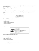
System Specifications Electrical Specifications Table 1-6 PDCA Product Number Available Power Options (Continued) Source Type Source Voltage (nominal) PDCA Required Input Current Per Phase 200-240 VAC In-line Connector Required A5800A Option 005d 3-phase Voltage range 200-240 VAC, phase-to-neutral, 50/60 Hz (EUR typical) 5-wire 24A Maximum per phase In-line connector and plug provided with a 2.5-meter power cable. Electrician must hard-wire in-line connector to 60/63A site power.
System Specifications Electrical Specifications j. In the U.S.A., site power is 30 Amps; In Europe site power is 32 Amps. Table 1-7 Option 004 and 005 Specificsa PDCA Product Number Attached Power Cord Attached Plug Connector Provided A5800A Option 004 OLFLEX 190 (PN 600404) is a 2.5 meter multi conductor, 600 volt, 90 degree C, UL and CSA approved, oil resistant flexible cable.
System Specifications Electrical Specifications b. Panel-mount receptacles must be purchased by the customer from a local Mennekes supplier. c. In-line connector is available from HP by purchasing A6440A, Option 501. NOTE A qualified electrician must wire the PDCA in-line connector to site power using copper wire and in compliance with all local codes. Each branch circuit used within a Superdome Complex must be connected together to form a common ground.
System Specifications Electrical Specifications WARNING Do not install a PDCA that does not have one of the following set of labels attached.
System Specifications Electrical Specifications Figure 1-5 PDCA Locations L Bezel PDCA 0 PDCA 1 Rear PDCA Bezel L Bezel 60SP040B 11/15/01 Power Cords This section discusses the different possibilities for Superdome PDCA power cords. Pre-wired PDCAs Options 6 and 7 All Superdomes are delivered with the appropriate cable and plug. The mating in-line connector is not provided. IMPORTANT Verify that the source power is correct for the appropriate PDCA wiring.
System Specifications Electrical Specifications • To verify the proper wiring for a 4-wire PDCA, use a DVM to measure the voltage at the in-line connector. Voltage should read 200 - 240 Vac phase-to-phase as measured between the connector pins as follows: L1 to L2, L2 to L3, L1 to L3. • To verify the proper wiring for a 5-wire PDCA, use a DVM to measure the voltage at the connector.
System Specifications Electrical Specifications IMPORTANT Ensure that your DVM is capable of measuring AC voltages of at least 500VAC. A number of 5-wire power distribution systems may have phase-to-phase voltages in excess of 400VAC. Many hand-held volt meters are limited to 300VAC.
System Specifications Electrical Specifications To remove the existing cable from the PDCA, begin be removing the five T-10 Torx screws detailed in Figure 1-9 on page 23. Then remove the bottom panel of the PDCA. Retain the panel and screws for future use. NOTE The cable removal and installation requires only the bottom panel to be removed. For image clarity, Figure 1-9 does not show cable or cable strain relief. Step 1. Locate and remove the PDCAs. Step 2.
System Specifications Electrical Specifications Step 5. Remove the cable from the PDCA. Keep all retaining hardware for use during installation of the new cable. Figure 1-9 PDCA Cable Access (5-Wire Unit Shown) L3-L1 L2-L3 L1-L2 L3 L2 L1 1.36 in DIA 3.
System Specifications Electrical Specifications Figure 1-10 PDCA Input Wiring Connections (5-Wire Unit Shown) L3-L1 L2-L3 L1-L2 N 60SP041A 7/13/00 Cable Installation NOTE These procedures may be used for early deliveries consisting of either option 1 or option 2 as well as those later systems delivered with PDCA cables attached. Select the proper cable using the following criteria. • Each Superdome cabinet using a 3-phase, 4-wire input is required to have a four-conductor cable.
System Specifications Electrical Specifications Step 5. Using the five screws retained from the removal procedure, replace the bottom panel on the PDCA. Refer to Figure 1-9 on page 23 for panel installation details. Step 6. To verify the proper wiring to a 4-wire PDCA, use a DVM to measure the voltage at the test points. Voltage should read 200 - 240 Vac phase-to-phase as measured between the test points as follows: L1 to L2, L2 to L3, L1 to L3.
System Specifications Electrical Specifications NOTE Figure 1-12 Figure 1-11 shows a 4-wire cable for illustrative purposes only. 5-wire cable is dimensionally identical regarding insulation and jacket removal. The only exception is the number of conductors.
System Specifications Electrical Specifications Customer Installation Options Figure 1-14 and Figure 1-15 detail a suggested configuration for connecting the PDCA when the use of rigid conduit is required or desired. Using a 2- to 4-inch nipple and a 90o elbow allows the conduit to pass through the raised floor at a point immediately past the cabinet. This prevents the conduit from extending beyond the cabinet.
System Specifications Electrical Specifications System Power Requirements Table 1-9 and Table 1-10 list the AC power requirements for a Superdome. These tables provide information to help determine the amount of AC power needed for your computer room.
System Specifications Electrical Specifications I/O Expansion Cabinet Power Requirements The I/O expansion cabinet requires a single phase 200-240VAC input. Table 1-11 lists the AC power requirements for the I/O expansion cabinet.
System Specifications Electrical Specifications Support Management Station Power Requirements Refer to the applicable documentation for the SMS power requirements.
System Specifications Environmental Requirements Environmental Requirements This section provides the environmental, power dissipation, noise emission, and air flow specifications for the Superdome. Temperature and Humidity Specifications Ambient intake air temperature is often different from ambient room temperature. You should measure the operating temperature and humidity directly in front of the cabinet cooling air intakes rather than check only ambient room conditions.
System Specifications Environmental Requirements Support Management Station Power Dissipation Refer to the applicable documents for the test station power dissipation. Acoustic Noise Specification The acoustic noise specification for the Superdome is as follows: • 8.2 bel (sound power level) • 65.1 dBA (sound pressure level at operator position) The above levels are appropriate for dedicated computer room environments, not office environments.
System Specifications Environmental Requirements Figure 1-17 on page 34 through Figure 1-19 on page 36 illustrate typical cooling system layouts, adapted from the typical cooling system described in Chapter 2.
System Specifications Environmental Requirements Figure 1-17 Typical Superdome Room Space Return Air Cooling System Roof or floor slab above Ceiling cavity Ceiling Room space return air (RSRA) Down-flow A/C equipment Raised floor Floor cavity supply plenum Computer air intake Floor slab Perforated floor panel (typical) 60SP005A 4/17/00 34 Chapter 1
System Specifications Environmental Requirements Figure 1-18 Typical Superdome Ducted Return Air Cooling System Roof or floor slab above Ceiling cavity Ducted return air (DRA) Ceiling Down-flow A/C equipment Cooled supply air Floor cavity supply plenum Computer air intake Perforated floor panel (typical) Raised floor Floor slab Chapter 1 60SP006A 4/17/00 35
System Specifications Environmental Requirements Figure 1-19 Typical Superdome Ceiling Plenum Return Air Cooling System To and from air handling unit (if used) Supply air ductwork Roof or floor slab above Return air grille Ceiling plenum return air (CPRA) Ceiling diffuser (typical) Up-flow A/C equipment Ceiling Computer air discharge (typical) Computer air intake Cooled supply air 60SP007A 12/16/99 36 Chapter 1
2 Electrical and Environmental Guidelines This chapter provides guidelines for planning and preparing the site. Careful site planning and preparation ensures trouble-free installation and reliable operation of Superdome servers. Factors that may contribute to less than optimal equipment operation are also highlighted. • “Electrical Factors” on page 39 discusses computer room safety, electrical load requirements, power quality, distribution hardware, and system installation guidelines.
Electrical and Environmental Guidelines • 38 “Environmental Elements” on page 44 discusses computer room preparation, cooling and humidity requirements, dust and pollution control, electrostatic discharge prevention, and acoustics.
Electrical and Environmental Guidelines Electrical Factors Electrical Factors Proper design and installation of a power distribution system for a Superdome server requires specialized skills. Those responsible for this task must have a thorough knowledge and understanding of appropriate electrical codes and the limitations of the power systems for computer and data processing equipment. In general, a well-designed power distribution system exceeds the requirements of most electrical codes.
Electrical and Environmental Guidelines Electrical Factors The minimum recommended illumination level is 70 foot-candles (756 lumens per square meter) when the light level is measured at 30 inches (76.2 cm) above the floor. Power Quality This equipment is designed to operate over a wide range of voltages and frequencies. It has been tested and shown to comply with EMC Specification EN50082. However, damage can occur if these ranges are exceeded.
Electrical and Environmental Guidelines Electrical Factors Distribution Hardware This section describes wire selection and the types of raceways (electrical conduits) used in the distribution system. Wire size is dictated by circuit breaker sizing and local safety codes. Wire Selection Use copper conductors instead of aluminum, as aluminum’s coefficient of expansion differs significantly from that of other metals used in power hardware.
Electrical and Environmental Guidelines Electrical Factors Main Building Electrical Ground The main electrical service entrance equipment should have an earth ground connection, as required by applicable codes. Connections such as a grounding rod, building steel, or a conductive type cold water service pipe provide an earth ground.
Electrical and Environmental Guidelines Electrical Factors Wiring connections must be properly torqued. Many equipment manufacturers specify the proper connection torque values for their hardware. Ground connections must only be made on a conductive, nonpainted surface. Lockwashers must be used on all connections to prevent connection hardware from working loose. Data Communications Cables Power transformers and heavy foot traffic create high energy fields.
Electrical and Environmental Guidelines Environmental Elements Environmental Elements The following environmental elements can affect a Superdome server installation: • Computer room preparation • Cooling requirements • Humidity level • Air conditioning ducts • Dust and pollution control • Electrostatic discharge (ESD) prevention • Acoustics (noise reduction) • Zinc whisker control Computer Room Preparation The following guidelines are recommended when preparing a computer room for a Superd
Electrical and Environmental Guidelines Environmental Elements • System controls adequate to maintain the computer room within the operating ranges listed in Table 2-1. Table 2-1 Parameter Computer Room Environment Operating Range Temperaturea,b 68° to 86° F (20° to 30° C) Humidity 15% - 80% with no condensation (40% - 55% recommended) Recommended Range 68 to 72 °F (20° to 23° C) Maximum Rate of Change (per hour) 9° F repetitive, 36° F nonrepetitive (5° C repetitive, 20° C nonrepetitive) 6% a.
Electrical and Environmental Guidelines Environmental Elements Basic Air Distribution Systems A basic air distribution system includes supply air and return air. An air distribution system should be zoned to deliver an adequate amount of supply air to the cooling air intake vents of the computer system equipment cabinets. Supply air temperature should be maintained within the following parameters: • Ceiling supply system—From 55° F (12.8° C) to 60° F (15.6° C) • Floor supply system—At least 60° F (15.
Electrical and Environmental Guidelines Environmental Elements Figure 2-4 on page 50 illustrates a typical computer room above ceiling ducted air distribution system (DRA).
Electrical and Environmental Guidelines Environmental Elements Figure 2-2 Underfloor Air Distribution System Roof or floor slab above Ceiling cavity Ducted return air (DRA) Ceiling Down-flow A/C equipment Cooled supply air Floor cavity supply plenum Computer air intake Perforated floor panel (typical) Raised floor Floor slab 48 60SP006A 4/17/00 Chapter 2
Electrical and Environmental Guidelines Environmental Elements Figure 2-3 Ceiling Plenum Air Distribution System To and from air handling unit (if used) Supply air ductwork Roof or floor slab above Return air grille Ceiling plenum return air (CPRA) Ceiling diffuser (typical) Up-flow A/C equipment Ceiling Computer air discharge (typical) Computer air intake Cooled supply air 60SP007A 12/16/99 Chapter 2 49
Electrical and Environmental Guidelines Environmental Elements Figure 2-4 Above Ceiling Ducted Air To and from air handling unit (if used) Roof or floor slab above Supply air ductwork Ducted return air (DRA) Return air grille Ceiling diffuser (typical) Up-flow A/C equipment Ceiling Slab floor Computer air discharge (typical) Computer air intake Cooled supply air 60SP015A 4/17/00 Humidity Level Maintain proper humidity levels.
Electrical and Environmental Guidelines Environmental Elements CAUTION Low humidity contributes to undesirably high levels of electrostatic charges. This increases the electrostatic discharge (ESD) voltage potential. ESD can cause component damage during servicing operations. Paper feed problems on high-speed printers are usually encountered in low-humidity environments. Low humidity levels are often the result of the facility heating system and occur during the cold season.
Electrical and Environmental Guidelines Environmental Elements Special precautions are necessary if the computer room is near a source of air pollution. Some air pollutants, especially hydrogen sulfide (H2S), are not only unpleasant but corrosive as well. Hydrogen sulfide damages wiring and delicate sound equipment. The use of activated charcoal filters reduces this form of air pollution. Zinc Particulate Contamination Metallic particulates can be especially harmful around electronic equipment.
Electrical and Environmental Guidelines Environmental Elements Static Protection Measures Follow these precautions to minimize possible ESD-induced failures in the computer room: • Install conductive flooring (conductive adhesive must be used when laying tiles). • Use conductive wax (if waxed floors are necessary). • Ensure that all equipment and flooring are properly grounded and are at the same ground potential. • Use conductive tables and chairs.
Electrical and Environmental Guidelines Environmental Elements 54 Chapter 2
3 Facility Guidelines This chapter describes facility characteristics and provides guidelines for preparing the computer room. • “Facility Characteristics” on page 57 discusses architectural issues. • “Space Requirements” on page 60 discusses the amount of floor space required by the components.
Facility Guidelines NOTE 56 Refer to Appendix C for templates to aid in locating caster contact area and caster/leveling foot centers. Templates are also provided to locate required cutouts for cable routing.
Facility Guidelines Facility Characteristics Facility Characteristics This section contains information about facility characteristics that must be considered for the installation or operation of a Superdome server. Facility characteristics are: • Floor loading • Windows • Altitude effects Floor Loading The computer room floor must be able to support the total weight of the installed computer system as well as the weight of the individual cabinets as they are moved into position.
Facility Guidelines Facility Characteristics Table 3-1 Floor-Loading Terms (Continued) Term Definition Concentrated load Load a floor panel can support on a 1-in2 (6.45 cm2) area at the panel’s weakest point (typically the center of the panel), without the surface of the panel deflecting more than a predetermined amount. Ultimate load Maximum load (per floor panel) the floor system can support without failure. Failure expressed by floor panel(s) breaking or bending.
Facility Guidelines Facility Characteristics In the event that the flooring is being replaced or a new floor is being installed, Tate Access Floors recommends its Series 1250 all-steel access floor with bolt-together stringers and 24 in. (61.0 cm) by 24 in. (61.0 cm) floor panels be used to support the Superdome installation.
Facility Guidelines Space Requirements Space Requirements This section contains information about space requirements for a Superdome server. This data should be used as the basic guideline for space plan developments. Other factors, such as airflow, lighting, and equipment space requirements, must also be considered. Delivery Space Requirements There should be enough clearance to move equipment safely from the receiving area to the computer room.
Facility Guidelines Space Requirements • Access areas for power wiring and air conditioning filters • Equipment cable routing Copies of the floor plan grid are located in Appendix C. Equipment Footprint Templates Equipment footprint templates are provided in Appendix C to show basic equipment dimensions and space requirements for servicing. Be sure to use the appropriate templates for the equipment that is to be installed. The service areas shown on the template drawings are lightly shaded.
Facility Guidelines Space Requirements 62 Chapter 3
4 Pre-Installation Survey This chapter provides a site survey information packet consisting of an information form and checklists to be used to evaluate a computer facility. The checklists information sheets and information forms should be filled out by the customer and a Hewlett-Packard representative. • “Pre-Installation Survey Content” on page 65 describes the contents of the site survey information packet.
Pre-Installation Survey • “Typical Installation Schedule” on page 66 describes the proposed schedule of installation events. • “Site Inspection” on page 67 provides a sample pf the on-site inspection checklist. • “Delivery Survey” on page 71 provides the delivery or installation requirement forms.
Pre-Installation Survey Pre-Installation Survey Content Pre-Installation Survey Content The site pre-installation survey information is designed to identify problems that might occur before, during, or after the installation of the system. It contains the following items: • Pre-installation checklists—Verify the customer site is ready for the equipment installation. • Pre-installation survey information sheets—List customer name, address, and corresponding Hewlett-Packard sales personnel.
Pre-Installation Survey Typical Installation Schedule Typical Installation Schedule The following schedule lists the sequence of events for a typical system installation: • 60 days before installation — Floor plan design completed and mailed to Hewlett-Packard • 30 days before installation — Primary power and air conditioning installation completed — Telephone and data cables installed — Fire protection equipment installed — Major facility changes completed — Special delivery requirements defined — Site
Pre-Installation Survey Site Inspection Site Inspection Table 4-1 contains a sample of the Customer and Hewlett-Packard information required. Table 4-2 contains a sample site inspection checklist. IMPORTANT Ensure that the customer is aware of the iCOD email requirements. That is, each bootable partition requires a connection to the internet to send email to notify Hewlett-Packard that the customer has allocated additional CPUs beyond the amount initially purchased.
Pre-Installation Survey Site Inspection To ensure compliance with item 10 of Table 4-2, provide a copy of Appendix D to the customer to use a worksheet to identify required names and addresses for the LAN. NOTE Table 4-2 Site Inspection Checklist Please check either Yes or No. If No, include comment or date Comment or Date Computer room No. Area or condition 1. Is there a completed floor plan? 2. Is there adequate space for maintenance needs? Front 42 in (106 cm) min.
Pre-Installation Survey Site Inspection Table 4-2 Site Inspection Checklist (Continued) Please check either Yes or No. If No, include comment or date 11. Are floor tiles in good condition and properly braced? 12. Metallic particulate test required. Comment or Date Power and lighting No. Area or condition 13. Are lighting levels adequate for maintenance? 14. Are there ac outlets available for servicing needs? (i.e. vacuuming) 15.
Pre-Installation Survey Site Inspection Table 4-2 Site Inspection Checklist (Continued) Please check either Yes or No. If No, include comment or date 26. Comment or Date Are there any equipment servicing hazards (loose ground wires, poor lighting, etc.)? Cooling No. Area or condition 27. Can cooling be maintained between 68° and 86° (20° and 30° C)? 28. Can temperature changes be held to 9° (5 ° C) per hour? 29. Can humidity level be maintained between 40% and 55%? 30.
Pre-Installation Survey Delivery Survey Delivery Survey The delivery survey form shown in Figure 4-1 on page 72 and Figure 4-2 on page 73 lists delivery or installation requirements. If any of the items on the list apply, enter the appropriate information in the areas provided on the form. Special instructions or recommendations should be entered on the Special Instructions or Recommendations form.
Pre-Installation Survey Delivery Survey Figure 4-1 Delivery Survey (Part 1) DELIVERY CHECKLIST DOCK DELIVERY Yes Is dock large enough for a semitrailer? No Circle the location of the dock and give street name if different than address. North East West South STREET DELIVERY Circle the location of access door and list street name if different than address. North East West South List height and width of access door. List special permits (if required) for street delivery.
Pre-Installation Survey Delivery Survey Figure 4-2 Delivery Survey (Part 2) ELEVATOR Fill in the following information if an elevator is required to move equipment. Capacity (lb or kg) Depth Height Width Height Depth Width STAIRS Please list number of flights and stairway dimensions.
Pre-Installation Survey Delivery Survey 74 Chapter 4
A System Weights Appendix A 75
System Weights Weight Weight To determine overall weight, follow the examples in Table A-1, then complete the entries in Table A-2. Table A-1 Example Weight Summary Component Quantity Multiply By Weight (kg) Chassisa 1 745.17 lbs (338.10) 745.17 lbs (338.10) Cell Boards 4 41.00 lbs (18.60) 164.00 lbs (74.40) DIMMs 128 .2 lbs 25.60 (11.60) (.09) I/O Cardcages 4 36.5 lbs (16.56) 146 lbs (66.24) I/O Cards 12 .45 lbs (.225) 5.4 lbs (2.45) PDCA 2 26.00lbs (23.59) 104.00 lbs (47.
System Weights Weight Table A-2 Component Weight Summary (Continued) Quantity Multiply By Weight (kg) PDCA 26.00lbs (23.59) lbs Bulk Power Supply (BPS) 23.00 lbs (11.81) lbs Total weight lbs a. The listed weight for a chassis includes the weight of all components not listed in Table A-2.
System Weights Weight 78 Appendix A
B Conversion Factors The conversion factors provided in this appendix are intended to ease data calculation for systems that do not conform specifically to the configurations listed in this Site Preparation Guide. Listed below are the conversion factors used in this document, as well as additional conversion factors that may be helpful in determining those factors required for site planning.
Conversion Factors • Refrigeration — 1 watt = .86 kcal/h — 1 watt = 3.413 Btu/h — 1 watt = 2.843-4 tons — 1 ton = 200 Btu/min — 1 ton = 12,000 Btu/h — 1 ton = 3,517.2 W • Metric equivalents — 1 centimeter = 0.3937 in — 1 meter = 3.28 ft — 1 meter = 1.09 yds — 1 in. = 2.54 cm — 1 ft = 0.305 m — 1 CFM = 1.
C Templates This appendix contains blank floor plan grids and equipment templates. Combine the necessary number of floor plan grid sheets to create a scaled version of the computer room floor plan. Figure C-1 illustrates the locations required for the cable cutouts. Figure C-2 on page 83 illustrates the overall dimensions required for a Superdome 32 Way system.
Templates Figure C-3 on page 84 illustrates the overall dimensions required for a Superdome 64 Way system. Figure C-1 Cable Cutouts and Caster Locations 14 in 35.6 cm 5.1 in 13.0 cm (edge of cutout) 3.8 in 9.5 cm (center of foot) 7 in 1 in 17.8 cm Service 7 in Area 17.8 cm 2.5 cm Server 4X Leveling feet 1.25" dia 3.2 cm Rear Door 36 in 91.4 cm 48 in 122 cm 126 in 320 cm IO Cable Exit 4X Caster 7 in 17.8 cm 7.8 in 19.9 cm Service Area 5.1 in 12.8 cm 30 in 76.2 cm 42 in 106.
Templates Figure C-2 Superdome 16 Way/Superdome 32 Way Space Requirements NOTE: 12" Minimum Clearance Required Between Top Of Cabinet and Ceiling 4 ft 1220 mm 126 in 320 cm Server Service Area 30 in 762 mm 36 in 91.4 cm Service Area 6.4 ft 1.95 m 48 in 122.0 cm 42 in 106.7 cm NOTE: 48 in Is Recommended 42 in Is Minimum Allowable 30 in 76.
Templates Figure C-3 Superdome 64 Way Space Requirements NOTE: 12" Minimum Clearance Required Between Top Of Cabinet and Ceiling 77 in 196 cm 48 in 122 cm 60 in 152.4 cm 36 in 91.4 cm Service Area Server Server 126 in 320 cm Service Area 48 in 122.0 cm 42 in 106.7 cm NOTE: 48 in Is Recommended 42 in Is Minimum Allowable 60 in 152.
Templates Equipment Footprint Templates Equipment Footprint Templates Equipment footprint templates are drawn to the same scale as the floor plan grid (1/4 inch = 1 foot). These templates are provided to show basic equipment dimensions and space requirements for servicing. The service areas shown on the template drawings are lightly shaded. The equipment templates should be used with the floor plan grid to define the location of the equipment that will be installed in your computer room.
Templates Computer Room Layout Plan Computer Room Layout Plan Use the following procedure to create a computer room layout plan: Step 1. Remove several copies of the floor plan grid. Step 2. Cut and join them together (as necessary) to create a scale model floor plan of your computer room. Step 3. Remove a copy of each applicable equipment footprint template. Step 4. Cut out each template selected in Step 3; then place it on the floor plan grid created in Step 2. Step 5.
Templates Computer Room Layout Plan Superdome 32 Way, Superdome 64 Way, and I/O Expansion Cabinet Templates Scale: 1/4 inch = 1 foot Service Area Server Service Area Server Server Service Area Service Area Service Area Service Area Server Service Area Server Server Service Area IOX Cabinet Service Area Service Area IOX Cabinet Service Area Service Area 60SP017A 7/16/00 Appendix C 87
Templates Computer Room Layout Plan Superdome 32 Way, Superdome 64 Way, and I/O Expansion Cabinet Templates Scale: 1/4 inch = 1 foot Service Area Server Service Area Server Server Service Area Service Area Service Area Service Area Server Service Area Server Server Service Area IOX Cabinet Service Area Service Area IOX Cabinet Service Area Service Area 60SP017A 7/16/00 88 Appendix C
Templates Computer Room Layout Plan Superdome 32 Way, Superdome 64 Way, and I/O Expansion Cabinet Templates Scale: 1/4 inch = 1 foot Service Area Server Service Area Server Server Service Area Service Area Service Area Service Area Server Service Area Server Server Service Area IOX Cabinet Service Area Service Area IOX Cabinet Service Area Service Area 60SP017A 7/16/00 Appendix C 89
Templates Computer Room Layout Plan Superdome 32 Way, Superdome 64 Way, and I/O Expansion Cabinet Templates Scale: 1/4 inch = 1 foot Service Area Server Service Area Server Server Service Area Service Area Service Area Service Area Server Service Area Server Server Service Area IOX Cabinet Service Area Service Area IOX Cabinet Service Area Service Area 60SP017A 7/16/00 90 Appendix C
Templates Computer Room Layout Plan Superdome 32 Way, Superdome 64 Way, and I/O Expansion Cabinet Templates Scale: 1/4 inch = 1 foot Service Area Server Service Area Server Server Service Area Service Area Service Area Service Area Server Service Area Server Server Service Area IOX Cabinet Service Area Service Area IOX Cabinet Service Area Service Area 60SP017A 7/16/00 Appendix C 91
Templates Computer Room Layout Plan Superdome 32 Way, Superdome 64 Way, and I/O Expansion Cabinet Templates Scale: 1/4 inch = 1 foot Service Area Server Service Area Server Server Service Area Service Area Service Area Service Area Server Service Area Server Server Service Area IOX Cabinet Service Area Service Area IOX Cabinet Service Area Service Area 60SP017A 7/16/00 92 Appendix C
Templates Computer Room Layout Plan Scale: 1/4 inch = 1 foot 60SP016A 12/20/99 Appendix C 93
Templates Computer Room Layout Plan Scale: 1/4 inch = 1 foot V25U067 10/2/98 94 Appendix C
Templates Computer Room Layout Plan Scale: 1/4 inch = 1 foot V25U067 10/2/98 Appendix C 95
Templates Computer Room Layout Plan Scale: 1/4 inch = 1 foot 60SP016A 12/20/99 96 Appendix C
Templates Computer Room Layout Plan Scale: 1/4 inch = 1 foot V25U067 10/2/98 Appendix C 97
Templates Computer Room Layout Plan 98 Appendix C
D Superdome LAN Interconnect Diagram Have the customer fill in Table D-1 on page 100 with LAN information. Use the following diagram to help correlate the LAN connection with the IP address.
Superdome LAN Interconnect Diagram • Console port on SMS • Customer network interface on SMS (10/100 Base-T Port) • Each network interface on each partition • PC/Workstation console Table D-1 LAN Information LAN Port: SDa GSP Private Hostname (GSP Network Name) IP Address Subnet Mask Gateway Address Priv-nn (where nn is 01, 02, 03, ...) 192.168.2.1n (where n is 1, 2, 3, ...) 255.255.255.0 192.168.2.1n (where n is 1, 2, 3, ...) PrivateM 192.168.2.10M (where M is 1, 2, 3, ...) 255.255.
Superdome LAN Interconnect Diagram Table D-1 LAN Information (Continued) LAN Port: Hostname (GSP Network Name) IP Address Subnet Mask Gateway Address Partition 5 (Net Interface 1) Partition 5 (Net Interface 2) Partition 5 (Net Interface 3) a. Superdome b.
Superdome LAN Interconnect Diagram 102 Appendix D
E Superdome Configurations Table E-1 shows Superdome power requirements by configuration (i.e. number of cell boards, amount of memory per cell, and number of I/O chassis). This requirement applies to 32-way-capable systems with PA8600 or PA8700 processors.
Superdome Configurations There are two columns of power numbers (Watts). The Power Breaker column shows the power used to size the wall breaker at the installation site. The Typical Power column shows typical power. Typical power numbers are for PA8600 systems and may be used to assess average utility cost of cooling and electrical power. Expect these typical numbers to be about 18% less for PA8700 systems. Table E-1 also shows the recommended breaker sizes for 4-wire and 5-wire sources.
Superdome Configurations b. An input power source supplied from a 3-pole plus protective earth (PE), 4-wire system will always be wired as 240 volts phase-to-phase, no neutral or common, plus a PE ground. Three phase input voltage (240VAC) to the equipment is connected phase-to-phase. Examples of 4 wire: 200-volt phase-to-phase, 208-volt phase-to-phase, 240-volt phase-to-phase c.
Superdome Configurations 106 Appendix E