
Site Preparation Guide, Eighth Edition - Superdome HP 9000 Systems


Appendix C
Te mp la t e s
82
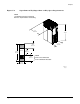
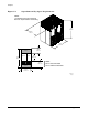
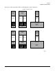
Figure C-3 on page 84 illustrates the overall dimensions required for a Superdome 64 Way system.
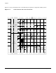
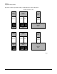
Figure C-1 Cable Cutouts and Caster Locations
6/16/00
60SP028A
122 cm
76.2 cm
30 in
Service
Area
126 in
320 cm
Server
Area
Service
36 in
91.4 cm
48 in
106.7 cm
42 in
Rear Door
17.8 cm
7 in
4X Leveling feet
IO Cable Exit
1 in
2.5 cm
1.25" dia
14 in
35.6 cm
5.1 in
12.8 cm
7.8 in
19.9 cm
4X Caster
3.2 cm
NOTE:
48 in Is Recommended
42 in Is Minimum Allowable
(48 in)
(122 cm)
13.0 cm (edge of cutout)
5.1 in
9.5 cm (center of foot)
3.8 in
7 in
17.8 cm
17.8 cm
7 in