
Site Preparation Guide, Eighth Edition - Superdome HP 9000 Systems

Chapter 1
System Specifications
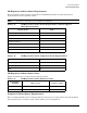
Electrical Specifications
22
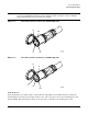
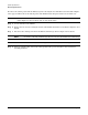
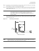
To remove the existing cable from the PDCA, begin be removing the five T-10 Torx screws detailed in Figure
1-9 on page 23. Then remove the bottom panel of the PDCA. Retain the panel and screws for future use.
NOTE The cable removal and installation requires only the bottom panel to be removed. For image
clarity, Figure 1-9 does not show cable or cable strain relief.
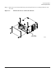
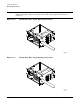
Step 1. Locate and remove the PDCAs.
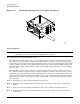
Step 2. Remove the five screws securing the bottom of the PDCA. Retain the screws. Refer to Figure 1-9 for
details.
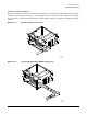
Step 3. Disconnect the existing wires from the PDCA terminal lugs. Refer to Figure 1-9 for details.
NOTE Loosen the cable side terminal lugs only. Do not loosen the PDCA side terminal lugs.
NOTE For 5-wire cables, loosen four lugs. For 4-wire cables, loosen three lugs.
Step 4. Using an 11-mm socket, remove the safety ground cable (green and yellow cable). Retain the
attaching hardware.