
Site Preparation Guide, Eighth Edition - Superdome HP 9000 Systems


Chapter 1
System Specifications
Electrical Specifications
24
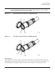
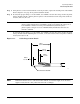
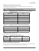
Figure 1-10 PDCA Input Wiring Connections (5-Wire Unit Shown)
Cable Installation
NOTE These procedures may be used for early deliveries consisting of either option 1 or option 2 as
well as those later systems delivered with PDCA cables attached.
Select the proper cable using the following criteria.
• Each Superdome cabinet using a 3-phase, 4-wire input is required to have a four-conductor cable. The
four-conductor cable selected by the facility electrician shall be in accordance with local electrical codes to
support the selected circuit breaker for the maximum Product Label current of 44A per phase. The facility
electrician and local electrical codes will determine proper power cord selection dependent upon desired
application such as rigid conduit, flexible conduit, or cable bundle. Observe derating factors for multiple
wires per cable.
• Each Superdome cabinet using a 3-phase 5-wire input is required to have a five-conductor cable. The
five-conductor cable selected by the facility electrician shall be in accordance with local electrical codes to
support the selected circuit breaker for the maximum Product Label current of 24A per phase. The facility
electrician and local electrical codes will determine proper power cord selection dependent upon desired
application such as rigid conduit, flexible conduit, or cable bundle. Observe derating factors for multiple
wires per cable.
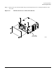
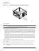
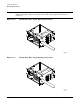
Step 1. Prepare the new cable as shown in Figure 1-11 on page 25.
Step 2. Using the cable retaining hardware saved from the cable removal, route the new cable into the
PDCA.
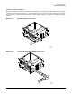
Step 3. Route the cable into the PDCA terminal lugs and secure in position by tightening the lugs.
Step 4. Using the hardware that was retained during the cable removal, attach the green and yellow
ground cable.
7/13/00
60SP041A
L
3
-L
1
L
2
-L
3
L
1
-L
2
N