
Site Preparation Guide, Eighth Edition - Superdome HP 9000 Systems


Chapter 1
System Specifications
Electrical Specifications
25
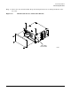
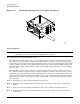
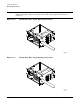
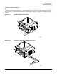
Step 5. Using the five screws retained from the removal procedure, replace the bottom panel on the PDCA.
Refer to Figure 1-9 on page 23 for panel installation details.
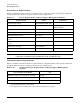
Step 6. To verify the proper wiring to a 4-wire PDCA, use a DVM to measure the voltage at the test points.
Voltage should read 200 - 240 Vac phase-to-phase as measured between the test points as follows:
L1 to L2, L2 to L3, L1 to L3.
IMPORTANT In some electrical distributions around the world, it is possible to measure 415 VAC
phase-to-phase. Ensure that your DVM is capable of measuring AC voltages of at
least 500VAC. A number of 5-wire power distribution systems may have
phase-to-phase voltages in excess of 400VAC. Many hand-held volt meters are
limited to 300VAC.
To verify the proper wiring to a 5-wire PDCA, use a DVM to measure the voltage at the test points.
Voltage should read 200-240VAC phase-to-neutral, as measured between the test points as follows:
L1 to N, L2 to N, L3 to N.
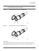
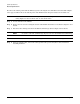
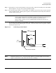
Figure 1-11 Cable Preparation Detail
NOTE Dimensions shown are for a cable strain relief without an extension nipple. If an extension
nipple is used, then the cable jacket must removed accordingly.
6
0
0.6 in
4.5 in
7.0 in
18 cm
11.5 cm
1.5 cm
1.5 cm
0.6 in
Ground Wire GN/YW