I/O Expansion Cabinet Guide For Superdome Servers Fourth Edition Manufacturing Part Number : A5201-10034 September 2006
Legal Notices The information in this document is subject to change without notice. Hewlett-Packard makes no warranty of any kind with regard to this manual, including, but not limited to, the implied warranties of merchantability and fitness for a particular purpose. Hewlett-Packard shall not be held liable for errors contained herein or direct, indirect, special, incidental or consequential damages in connection with the furnishing, performance, or use of this material. Restricted Rights Legend.
Preface iii
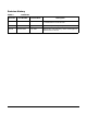
Revision History Table 1 Revision Revisions Part Number Release Date Description Fourth A5201-10034 September 2006 Added Chapter 8 which deals with IOX installation in a 10000 Series Universal Rack. Third A5201-10018 August 2001 Update Safety and Regulatory information. Second A5201-10015 July 2001 Added Safety and Regulatory section. Added general updates and corrections.
Safety and Regulatory Information For your protection, this product has been tested to various national and international regulations and standards. The scope of this regulatory testing includes electrical/mechanical safety, radio frequency interference, acoustics, and know hazardous materials.Where applicable, approvals obtained from third-party test agencies are shown on the product label.
WARNING Attach stabilizer feet to both front and back before extending the equipment drawers. Failure to attach the stabilizer feet may result in a tip hazard. WARNING Observe pinch hazard areas. Keep fingers away from closing parts. USA Radio Frequency Interference FCC Notice The Federal Communications Commission (in 47 CFR Part 15 subpart B) has specified that the following notice be brought to the attention of the users of this product.
5. Manufacturer/Nation: Figure 2 Certification Number: E - AAAAA - BB - CCCC • E: EMC registration • AAAAA: equipment codes (RRL notice, 2000.10.26) • BB: certification year • CCCC: registration number Figure 3 Korean RFI Translation Class A Equipment: Please note that this equipment has been approved for business purpose with regards to electromagnetic interference, if purchased un error for use in residential area, you may wish to exchange the equipment where you purchase it.
BSMI (Taiwan) This product is fully compliant to CNS 13438 (CISPR 22: 1993) Class A. The EMC label is in the form shown in Figure 4. The eight # signs represent an eight-character, alpha-number string. Figure 4 Figure 5 Acoustics (Germany) Acoustic Noise (A-weighted Sound Pressure Level LpA) measured at the bystander position, normal operation, to ISO 7779: LpA = 65.1 dB.
WARNING Please note the following conditions of installation: Install a PE (protective earthing) conductor that is identical in size, insulation material, and thickness to the branch-circuit supply conductors. The PE conductor insulation must be green with yellow stripes. The earthing conductor is to be connected from the unit to the building installation earth or, if supplied by a separately derived system, at the supply transformer or motor-generator set grounding point.
Australian C-Tick Label Figure 6 International Symbols (IEC335-1) Figure 7 Four Wire Connection Figure 8 Five Wire Connection Associated Documents The following documents provide more details on the topics presented in this manual: • Standard for the Protection of Electronic Computer Data Processing Equipment, (NFPA75) National Fire Protection Association • EIA Standard RS-232-C, Electronic Industries Association • Electrostatic Discharge Failures of Semiconductor Devices, Unger, B.A.
• IEC 60417, IEC 335-1, ISO 3864, IEC 617-2 International Symbols
Figure 9 I/O Expansion Cabinet Declaration of Conformity Page 1
Figure 10 I/O Expansion Cabinet Declaration of Conformity Page 2 xiii
xiv
1 Introduction The I/O Expansion (IOX) Cabinet provides additional I/O capacity for the Superdome 32, and 64 Way server. The IOX provides up to 72 Peripheral Controller Interface (PCI) slots in six 12-slot I/O chassis. Two IOX cabinets provide up to 96 PCI slots in eight 12-slot I/O chassis. There are two sizes of IOX cabinets: the 1.96-meter cabinet and the 1.6 meter cabinet.
Introduction Overview Overview Figure 1-1 illustrates a typical Superdome server and I/O cabinet installation. Shown are a Superdome 32 Way and one IOX cabinet. Figure 1-1 I/O Expansion Cabinet Shown With Superdome 64 Way Cabinet layout The IOX uses an HP modified Rosebowl rack: an RBII-D’ 19-inch cabinet.
Introduction Overview • I/O Expansion Power Chassis (XPC) • Rear Display Module (RDM) The four basic components can be further divided into controllers and functional units as shown in Table 1-1.
Introduction Overview ICE The ICE supports a maximum of two 12-slot I/O chassis. Each I/O chassis interfaces with an I/O Expansion Master I/O backplane (XMIOB) contained within an EMI enclosure and installed on the ICE tray. Figure 1-3 ICE Layout The ICE I/O tray slides forward out of the cabinet to allow access to the PCI slots. Cables are routed out of the front of the I/O chassis, underneath the chassis, and out the rear of the enclosure.
Introduction Overview The XMIOB routes necessary utilities signals from the utilities inlet connector. It also routes other utilities signals to the bridge connector. The XMIOB also has connectors to feed through REO and clock signals to the HIOB, as well as a connector and optional filter components for the chassis OL* LED signals. Chassis sheet metal and different connector sizes prevent illegal cable connection scenarios.
Introduction Overview I/O Chassis Each ICE can hold two 12-slot I/O chassis. PCI controller cards interface with cables that approach the I/O chassis from the front. Cables are attached to the PCI cards from the front of the I/O chassis. The chassis can be removed with or without extending the ICE tray. Figure 1-5 shows the I/O chassis being inserted into the ICE. Figure 1-5 I/O Chassis XUC The XUC provides utilities functions and clock distribution for components in the IOX.
Introduction Overview The XUC chassis external dimensions (excluding cosmetic panels and mounting flanges) are 119 mm (4.7 in) high by 425 mm (16.7 in) wide by 288 mm (11.3 in) deep. Figure 1-6 XUC XPC The XPC is a part of the AC-to-DC power subsystem. The AC-to-DC power subsystem comprises one or two Bulk Power Supplies (BPS) contained within one XPC.
Introduction Overview The power subsystem has n+1 redundancy for the AC-to-DC conversion and the AC inputs. AC-to-DC n+1 redundancy is achieved with two BPSs, any one of which can support the load. AC input redundancy is achieved with two single-phase AC power cords connected to dual (n+1) primary power grids, either one of which can support the load. Figure 1-7 XPC Location 60IOX012 11/17/00 A BPS is a modular, hot swappable, power supply that is installed into an XPC slot.
Introduction Overview NOTE Figure 1-8 The BPS for IOX is the same as that for Superdome.
Introduction Overview Additionally, each BPS accepts and generates control I/O interface signals from/to the Power Monitor Subsystem (PM3) assembly, which monitors and controls the power system. The PM3 detects the number and type of BPS modules present. If any of these modules fails, the PM3 may shut down the system dependent on the specific anomaly. The PM3 controls the On/Off status of the XPC +48Vdc rail.
Introduction Overview Table 1-3 I/O Expansion Cabinet Component Power Requirements Power Required (50 - 60 Hz) VA Fully configured cabinet 3200 I/O cardcage 500 ICE 600 The XPC distributes each single phase input to each BPS slot as shown in Figure 1-10.
Introduction IOX Visual Indicators IOX Visual Indicators This section outlines the visual indicators in the IOX. ICE Visual Indicators Indicators are provided on the ICE. I/O chassis Power and I/O chassis Attention LEDs are located on the center separator between the PCI card cages. The PCI Slot Power and PCI Slot Attention LEDs are located in the PCI card cage. Table 1-4 lists the visual indicators on the ICE. All indicators require some action before they can be displayed.
Introduction IOX Visual Indicators ICE Center Separator The separator in the ICE contains four LEDs: two for chassis 1 and two for chassis 3. See Figure 1-11. Figure 1-11 Center Separator If the chassis power is within the valid range, the Power LEDs are green.
Introduction IOX Visual Indicators PCI Card Separators Between each PCI card is a separator card. These cards indicate the voltage to each card. When the LED is green the voltage is within the valid range. If there is a problems, the LED is amber. See Figure 1-12. Figure 1-12 PCI Card Separators ICE Fan Status LEDs Each of the four ICE fans has a status LED. If the fan is functional the LED is green.
Introduction IOX Visual Indicators NOTE Figure 1-13 Chapter 1 There may be a delay of up to 60 seconds after turning on the 48V before the fan LEDs become active.
Introduction IOX Visual Indicators XPC visual Indicators The XPC houses two BPSs and each has a set of LEDs both on the front and rear. Figure 1-14 shows the front view of the BPSs. See Figure 1-14. Figure 1-14 BPS Front LEDs The meaning of each LED is given in Table 1-5. Table 1-5 XPC Font LED Definitions LED Definition AC0 Present On (amber) when AC is present on side A. Valid AC is line voltage is present at connector 1 AC1 Present On (amber) when AC is present on side B.
Introduction IOX Visual Indicators Front and Rear Displays IOX Control Panel Display (CPA) The CPA mounts on the front of the XUC. The CPA contains one XFPB (IOX Front Panel Board) and an attached 48V power on/off switch cable assembly. It provides a 1-1/2 digit cabinet number display (decimal), and LEDs for +5.3V Housekeeping Good and +48V Good. These are directly visible over a wide angle from the front of the IOX. The XFPB also has an ambient temperature sensor.
Introduction IOX Visual Indicators The rear door must be opened to view the RDM. Table 1-6 defines the RDM indicators. Table 1-6 Display RDM Display Location Additional Actions Required Cabinet Number Front surface Open rear door to maximize visibility 48V Power Front surface Open rear door to maximize visibility 5.
Introduction Cabinet Description Cabinet Description The IOX cabinet is a welded steel frame with removable top, rear doors, casters, leveling feet, and an anti-tip mechanism as shown in Figure 1-18. The top piece is 16-gauge, cold-rolled steel. The base piece is 11-gauge, hot-rolled steel. Threaded grounding studs are provided near the base of every column, and at the top rear. The cabinet itself is not grounded. Cabinet heights are measured in meters, inches, EIA units, and “U.
Introduction Cabinet Description The cabinet columns are a folded design made of 12-gauge rolled steel that supports up to 2000 lbs. Running up the inside of the fold are square mounting slots for the rails and screw holes for securing the rails. The hole placement conforms to EIA standards. The mounting columns are welded into place at the bottom corners of the frame and bolted at the top. The columns accept supporting rails into mounting slots.
Introduction Cabinet Description Heavy-Duty Casters Each cabinet is provided with four, 7.6-cm (3 in) diameter, smooth rolling, heavy-duty urethane casters to facilitate moves over short distances. The casters are rated at 454.5 kg (1000 lbs) per caster. Figure 1-19 Heavy-Duty Casters CAUTION Do not overload the raised floor. A fully loaded cabinet has a maximum gross weight of 995 kg (2188 lbs).
Introduction Cabinet Description Leveling Feet Four adjustable leveling feet come with the cabinet for stability and leveling. Levelers are located in each corner to level and stabilize the rack. For maximum accuracy, use a level while adjusting the feet. Figure 1-20 Leveling Feet Rear Door The rear door comes installed from the factory. Standard is a right-opening, perforated rear door with a lockable slam latch and sheet metal catch providing ventilation and security.
Introduction System Configurations System Configurations The allowed combinations of cabinet sizes, I/O chassis, slot totals, and free space for mounting other peripherals are summarized in Table 1-7. CAUTION Do not use the top 8U of the 1.96-meter cabinet to mount IOX components. Table 1-7 Cabinet Size Allowable Configurations XPC (pwr) XUC (utilities) 12-slot ICE Total number of I/O chassis Total # slots Free Rack Space 33 U (1.61m) 1 1 1 2 24 18 U 33 U (1.
Introduction System Configurations Peripheral Support All peripherals qualified for use with Superdome and/or for use in an RBII-D rack are supported in the IOX cabinet as long as there is available space. Peripherals not connected to or associated with the Superdome system to which the IOX is attached may be installed in the IOX. No servers except those required for Superdome system management such as test stations or High Availability Observatories may be installed in an IOX.
Introduction System Configurations Table 1-8 IOX Maximum Card and Cable Configurations (Continued) Card Description Cables per Card Cable type Max cards in 32W w/o IOX A4926A 1000B - SX 1 fiber pair 16 32 64 16 16 32 A4929A 1000B - T 1 UTP 16 32 64 16 16 32 A5513A ATM 155 (MMF) 1 fiber pair 8 16 32 8 8 16 A5515A ATM 155 (UTP5) 1 8-wire UTP 8 16 32 8 8 16 A5483A ATM 622 (MMF) 1 Fiber pair 8 16 32 8 8 16 A3739B FDDI Dual Attach 2 fiber pair 16 32
Introduction System Configurations Table 1-8 Card Part # J3593A IOX Maximum Card and Cable Configurations (Continued) Card Description Terminal MUX (64-port) Cables per Card Cable type Max cards in 32W w/o IOX 1 ??? 8 16 32 8 8 16 1 (8) ??? 8 16 32 8 (64) 8 (64) 16 (128) 0 N/A 8 16 32 0 0 0 Max cards in 32W w/IOX Max cards in 64W w/IOX Max Cables in 1 ICE Max Cables in 2 ICE Max Cables in 3 ICE Note 2:x slots only J3592A Terminal MUX (8-port) Note: 2x slots only A548
Introduction System Configurations Recommended Loading Order The recommended loading order of IOX components is to place the XPC as the lowest and the XUC and RDM as the highest IOX components in the rack. IOX components should occupy contiguous cabinet space. IMPORTANT Do not install any peripheral device between IOX modules.
Introduction System Configurations The required number of ICEs should be installed between the XPC and XUC/RDM. In this way, open rack space for peripherals is maximized. The recommended loading order for a 1.6m rack is shown in Figure 1-22, and the recommended loading order for the 1.96m rack is shown in Figure 1-23. Figure 1-22 1.6 Meter Rack Loading Figure 1-23 1.
Introduction System Configurations NOTE The IOX is shipped from the factory with all components installed in the recommended configuration. It should not be necessary to move components in the rack to accommodate adding an IOX (upgrade).If peripherals have been loaded, however, so that there are not 9U of contiguous rack space, it will be necessary to move peripherals to add the ICE.
Introduction System Configurations chassis in an ICE which are numbered 1 and 3 to match the numbering scheme in an I/O bay in the Superdome cabinet. XMIOBs are also numbered 1 and 3 to match the I/O chassis they serve. Figure 1-24 illustrates the logical component numbering for the IOX.
2 Upgrading the Superdome for IOX Whenever an IOX is connected to a Superdome server, the server must have special cable exit panels. These panels contain EMI proof cable clamps, called R-PEC for REO cables and U-PEC for GSP bus cables, through which these cables pass between the IOX and Superdome.
Upgrading the Superdome for IOX and Superdome require cutouts for the cables through which to pass. IOXs are shipped with skins that contain these cutouts. The “pre-IOX-release” Superdome servers require upgrading to skins with cutouts and cable exit panels. If the IOX connects to a Superdome 32 Way, you must determine to which side the IOX is connected. If two IOXs are connected to the Superdome 64 Way server, you must upgrade both cable exit panels. An IOX can also be connected to a Superdome 64 Way.
Upgrading the Superdome for IOX Removing Old Side Skins Removing Old Side Skins Step 1. Power down the Superdome server. Step 2. Remove the side (the on to which the IOX is to be connected) and rear blower bezels on each server cabinet. Figure 2-1Removing Blower Bezels NOTE Perform the following step only if installing the IOX on the rear-door-hinge side of the Superdome server. Step 3. If the rear door must be removed, perform the following steps. Otherwise, skip this step and go to Step 4.
Upgrading the Superdome for IOX Removing Old Side Skins 1. Remove the cable connected to the rear display cable located on the rear door, as shown in Figure 2-2. Figure 2-2Removing the Rear Display Cable 2. Remove the door grounding wire from the back channel, as shown in Figure 2-3.
Upgrading the Superdome for IOX Removing Old Side Skins NOTE The ground wire and/or connection point on your cabinet may be different to that shown in the figure. Figure 2-3Removing Rear Door Grounding Wire 3. Remove the rear door. Turn the door inward and lift it off its three hinges.
Upgrading the Superdome for IOX Removing Old Side Skins NOTE The door can only be lifted off the hinge pins by turning it inward as if you were partially closing it.
Upgrading the Superdome for IOX Removing Old Side Skins 4. Remove the rear door hinge plate by removing the six T20 Torx screws as shown in Figure 2-5. Figure 2-5Removing Door Hinge Screws Step 4. Remove the T20 screws that secure the side skin(s) to be removed. Figure 2-6 shows the left side skin (as viewed from the front of the server).
Upgrading the Superdome for IOX Removing Old Side Skins Step 5. Remove the appropriate side skin by sliding them out toward the back of the cabinet. See Figure 2-7.
Upgrading the Superdome for IOX Installing New Cable Exit Panel Installing New Cable Exit Panel Step 1. Remove old cable exit panel(s) on the appropriate side(s) of the Superdome cabinet. Both the left and right exit panels are shown in Figure 2-8. The exit panels are secured with two T20 Torx screws. Figure 2-8Removing Old Exit Panels Step 2. Remove the rear door latch from the old blank EMI panel and install it on the new panel.
Upgrading the Superdome for IOX Installing New Cable Exit Panel Step 3. Install the new cable exit panels into the appropriate side(s) of the panel. Secure the panel(s) with two T20 Torx screws. See Figure 2-9.
Upgrading the Superdome for IOX Installing the New Side Skins Installing the New Side Skins The new side skin(s) must be installed after the new exit panel(s). The Superdome side skin required for an IOX has a cutout that lines up with the cable feed clamps (R-PECs and U-PECS) in the new cable exit panel(s). Step 1. Locate the new side skin(s), remove it from the cardboard shipping container and remove the protective plastic wrap from the new side skin(s).
Upgrading the Superdome for IOX Installing the New Side Skins Step 2. Install the new side skin(s) in place of the old one(s). Install two T20 Torx screws at the top and bottom of the back of the side skin to secure.
Upgrading the Superdome for IOX Finishing the Upgrade Finishing the Upgrade Once the new exit panels are installed, the rear door (if removed), and blower bezel(s) must be reinstalled onto the Superdome cabinet(s). Perform the preceding procedures in reverse. Reinstalling the Rear Door NOTE Perform the following steps only if you had to remove the rear door to the Superdome cabinet. Step 1. Attach the door-hinge assembly using the six T20 Torx screws. Step 2.
Upgrading the Superdome for IOX Finishing the Upgrade 44 Chapter 2
3 Installing the IOX Chapter 3 45
Installing the IOX Unpacking the IOX Unpacking the IOX Before Unpacking the IOX The IOX is delivered in two boxes. The small box contains the IOX kick panel, cable exit panel, and other miscellaneous pieces. There are two tilt indicators on the large IOX box. Insure that they indicate that the box has not been subjected to damaging forces. Figure 3-1 Tilt Indicator Unpacking the IOX To unpack and set up the IOX into position, perform the following steps: Step 1.
Installing the IOX Unpacking the IOX WARNING Wear protective glasses while cutting the plastic bands around the shipping container. These bands are under tension. When cut, they can spring back and cause serious eye injury.
Installing the IOX Unpacking the IOX Step 3. Lift the cardboard top cap from the shipping box. Figure 3-3Removing the Cardboard Step 4. Remove the packing materials.
Installing the IOX Unpacking the IOX Step 5. Remove the cardboard box from the IOX using a box knife. See Figure 3-4. Figure 3-4Cutting the Packing Tape Step 6. Remove the bolt holding down the ramps and remove the ramps. See Figure 3-5.
Installing the IOX Unpacking the IOX Step 7. Remove the anti-tip stabilizer feet located under the front of the IOX by loosening the two shipping bolts using a 13-mm socket. This task may require a ratchet extension as the bolts are approximately 14 inches from the edge of the IOX. See Figure 3-6, Figure 3-7, and Figure 3-8.
Installing the IOX Unpacking the IOX Figure 3-8Removing the Anti-Tip Stabilizer Feet Step 8. Remove the power cord from the cabinet back rail by cutting the green tie-wraps on the rail and removing the green VELCRO ties holding the cord. NOTE Green tie-wraps and green VELCRO ties secure the cables during shipment. They should be removed when installing the IOX. The black tie-wraps and VELCRO ties should not be removed.
Installing the IOX Unpacking the IOX Step 9. Using the 13-mm socket and ratchet wrench, remove the four pallet securing brackets. Two are located toward the front of the cabinet, and two are located at the rear behind the anti-tip stabilizer feet. The anti-tip stabilizer feet must be removed (and are removed in Step 7. ) before these two pallets bolts can be removed. See Figure 3-10.
Installing the IOX Moving the IOX into Position Moving the IOX into Position After removing the packing materials, the pallet securing bolts, and the ramps, you are now ready to move the IOX into position. Step 1. Place the ramps onto the pallet. There are two slots in the wooden pallet into which the hooked ends of the ramps fit. The hooks and slots keep the ramps from sliding off the pallet while rolling the cabinet down the ramps.
Installing the IOX Moving the IOX into Position Step 2. Remove the middle side panels to expose the rack channels and rails. This allows you to grip firmly the IOX as you roll it down the ramps. Figure 3-12Remove Side Panels Before Rolling Cabinet onto Ramps Figure 3-13Exposing the Channels and Rails Step 3. While holding one of the side rails with one hand and the cabinet front with the other, carefully roll the IOX cabinet down the ramps. Two people are required to do this task. See Figure 3-14.
Installing the IOX Moving the IOX into Position WARNING Do not stand in front of the IOX while it is rolled down the ramps. It can fall on and injure you. WARNING Do not attempt to move the Superdome cabinet, either packed or unpacked, up or down an incline of more than 15ο. CAUTION Make sure that the leveling feet on the rack are raised before you roll the rack down the ramp and any time you roll the rack on the casters. CAUTION Use two people when rolling the cabinet down the ramps. Step 4.
Installing the IOX Aligning the IOX Cabinet to the Superdome Cabinet Aligning the IOX Cabinet to the Superdome Cabinet The IOX can be installed on either side of a Superdome server. Both the Superdome and the IOX cabinets, therefore, have pass-through cutouts that are covered by panels. Located on each side of the rack, these cutouts allow the IOX to be installed on either side of the Superdome cabinet. Figure 3-15 shows the panel removed in a Superdome server.
Installing the IOX Aligning the IOX Cabinet to the Superdome Cabinet NOTE Figure 3-16 Chapter 3 There are no mechanical features that hold the superdome and IOX in alignment.
Installing the IOX Aligning the IOX Cabinet to the Superdome Cabinet Step 1. Remove the cable exit cutout blank panel on the side of the Superdome server that is to be next to the IOX.
Installing the IOX Aligning the IOX Cabinet to the Superdome Cabinet Step 2. Remove the IOX exit panel blank on the side that is to be next to the Superdome server.
Installing the IOX Aligning the IOX Cabinet to the Superdome Cabinet Step 3. Install the IOX so that the front surface of the IOX side panel is in line with the front surface of the superdome side skin, as shown in Figure 3-19. Figure 3-19IOX Cabinet Alignment (Front) Step 4. Ensure that the cutout in the IOX rack extension panel aligns with the Superdome cable exit panel as shown in Figure 3-20.
Installing the IOX Securing the Cabinet Securing the Cabinet Step 1. Once in position, secure and stabilize the cabinet using the leveling feet at the corners of the base using the 13-mm open-end wrench. Remove the shipping band before adjusting the leveling foot. Figure 3-21Leveling Feet Step 2. Attach the anti-tip panels at the front and rear of the cabinet using the 13-mm socket and ratchet wrench.
Installing the IOX Securing the Cabinet Before attaching the front foot, be sure to mount the kick panel mounting bar as shown in Figure 3-22. The same screws that secure the anti-tip panel pass through the kick panel mounting bar. Figure 3-22Attaching the Anti-Tip Stabilizer Feet Step 3. Attach the kick panel at the base of the cabinet front as shown in Figure 3-23.
Installing the IOX Connecting the IOX to the Superdome Connecting the IOX to the Superdome Grounding the IOX to the Superdome After the IOX has been moved into place, it has to be grounded to the Superdome next to it. Provided with the IOX is a grounding cable with lugs on both ends. The following procedure describes how to connect the grounding cable. Step 1. Locate the grounding cable and determine which side of the rack to secure it. Figure 3-24IOX Grounding Strap Step 2.
Installing the IOX Connecting the IOX to the Superdome There are two lugs for this in both the IOX and Superdome server: one on either side of the cabinet. Secure the cable on to the side nearest the IOX. Figure 3-25Ground Studs in Superdome Cabinet Connecting the REO and GSP Bus Cables Overview The IOX is shipped with all cables connected.
Installing the IOX Connecting the IOX to the Superdome IMPORTANT Do not remove any black or grey cable ties. Figure 3-26 Remove and Discard Green VELCRO Ties There are optional brackets for retaining cables in the cable routing channel at the rear of the extension and additional holes for attaching cable ties in the routing channel.
Installing the IOX Connecting the IOX to the Superdome Examples of long cable runs are shown in Figure 3-28 where the cables run from IOX cabinet 8 to the far server cabinet n+1 and from IOX cabinet 9 to server cabinet n.
Installing the IOX Connecting the IOX to the Superdome Figure 3-29 Superdome 64 Way with Balanced IOX Cabinet Configuration SPU Cab (n) SPU Cab (n+1) IOX Cab (n+9) IOX Cab (n+8) Chassis Slots I/O Bay 1 0 1 I/O Bay 0 0 1 0 1 2 Chassis Slots Chassis Slots Chassis Slots 3 0 1 2 3 0 1 I/O Bay 1 0 1 I/O Bay 0 Front View (I/O Bays 0) 60IO890a 04/11/00 Connecting the REO Cables The following procedure describes how to connect and route an REO cable between the Superdome server and the
Installing the IOX Connecting the IOX to the Superdome There are two REO cables per ICE, and therefore REO cables are always connected in pairs. There are four R-PECs and one U-PEC in the cable exit panel. The REO cable pairs from the ICE mounted lowest should mount and run through the bottom R-PEC in the cable exit panel. Likewise, the REO cables from the next higher ICE pass through the next higher R-PEC, and so on.
Installing the IOX Connecting the IOX to the Superdome Step 2. Remove the rear door of the Superdome server. Step 3. Cut the green tie wraps and remove the green VELCRO ties holding the REO cables during shipment. NOTE The IOX may have one, two, or three ICEs. There are two REO cables per ICE. Therefore, you may have to perform these steps on as many as three REO cable pairs. Step 4. Remove the appropriate R-PEC from the cable exit panel by loosening the two T15 Torx screws.
Installing the IOX Connecting the IOX to the Superdome Step 5. Determine the destination in the Superdome server of the REO cable and pass the REO cable pair through the cable exit panel where the R-PEC was removed. Figure 3-33Passing the REO Cable Pair Through the Superdome Cable Exit Panel Step 6. Determine which shield protector to remove and pull the perforated section. Discard the plastic. The shield is exposed after the protector is removed. See Figure 3-34.
Installing the IOX Connecting the IOX to the Superdome IMPORTANT Remove the protective plastic only on the appropriate shield section. Leaving the other shield section exposed can cause inadvertent shorting. Figure 3-34REO Shield Exposed Step 7. Separate the halves of an R-PEC. You will have to loosen the screws in the blanks to facilitate their removal. The R-PEC attaches to the exposed shield in the REO cable. There are two halves that fasten together with three T15 Torx screws.
Installing the IOX Connecting the IOX to the Superdome IMPORTANT The R-PEC blanks must occupy all unused holes.
Installing the IOX Connecting the IOX to the Superdome Step 8. Attach the REO cable R-PEC to the cable at the exposed shield using two T15 Torx screws. See Figure 3-36. Figure 3-36Installing the R-PEC Step 9. Install the R-PEC in the appropriate location on the cable exit panel using two T20 Torx screws.
Installing the IOX Connecting the IOX to the Superdome IMPORTANT The three screws need to be tightened in the following sequence: middle first, then one side, and then the other side. Tighten each screw one turn at a time, repeating the sequence until all three are hand tight. This tightens the clamp onto the cable without warping. Figure 3-37REO Cable Pair Mounted in R-PEC and Installed in Cable Exit Panel Step 10. Connect the REO cable to the appropriate Cell board connector in the Superdome server.
Installing the IOX Connecting the IOX to the Superdome Step 11. Repeat Step 4. through Step 10. for each REO cable pair. Figure 3-38Typical REO Cable Locations Connecting the GSP Bus Cables The GSP bus cables are very similar to the REO cables, in that they have two sections where the shield is exposed. They are routed they same way as the REO cables and are secured to the Superdome cable exit panel with a U-PEC (as opposed the R-PEC used for the REO cables).
Installing the IOX Connecting the IOX to the Superdome Step 2. Remove the GSP bus U-PEC from the cable exit panel by removing the two T15 Torx screws. See figure Figure 3-40. In the figure the IOX is not in place for illustrative purposes. Figure 3-40Removing the GSP Bus U-PEC Step 3. Pass the GSP bus cable through the cable exit panel. Figure 3-41Passing the GSP Bus Cable Through the Cable Exit Panel Step 4. Determine which shield protector to remove and pull the perforated section.
Installing the IOX Connecting the IOX to the Superdome NOTE Remove the blue shield protector when the destination server is next to the IOX. Remove the green shield protector when the destination server is not next to it, as with a Superdome 64 Way server. IMPORTANT Remove the protective plastic only on the appropriate shield section. Leaving the other shield section exposed can cause inadvertent shorting. Figure 3-42GSP Bus Cable Shield Protector Step 5.
Installing the IOX Connecting the IOX to the Superdome IMPORTANT The U-PEC blanks must occupy all unused holes. Figure 3-43U-PEC Step 6. Attach the U-PEC to the GSP bus cable where the shield is exposed and tighten the two T15 Torx screws. Tighten the blank screws to seat the gasket.
Installing the IOX Connecting the IOX to the Superdome NOTE The U-PEC blanks are not round, so the correct orientation must be observed. They must be aligned properly to be able to close and tighten the U-PEC. Figure 3-44Proper Orientation of U-PEC Blank Figure 3-45Installing the GSP Bus U-PEC Step 7. Attach the U-PEC to the cable exit panel. Step 8. Connect the GSP bus cable to the Superdome server.
Installing the IOX Connecting the IOX to the Superdome You must determine where the GSP bus terminates in the Superdome. shows a typical installation. Figure 3-46Typical GSP Bus Installation in the Superdome Server Step 9. When finished installing the REO and GSP bus cables, reinstall the rear doors on both the IOX and Superdome sever(s).
Installing the IOX Setting the Cabinet Number Setting the Cabinet Number After installing the IOX, the cabinet number must be set. The IOX cabinet is either 8 or 9. to set the cabinet number: Step 1. Remove the XUC bezel by holding it with both hands on the handles on the side of the bezel and pulling forward. This exposes the XUC front panel. There are two latch screws on either side of the panel. Figure 3-48XUC Cosmetic Bezel Step 2. With a slotted screwdriver, turn the latch screws counter-clockwise.
Installing the IOX Setting the Cabinet Number Step 5. Locate the Cabinet Number switch and set it to the appropriate number. Figure 3-50Cabinet Number Switch IMPORTANT Never have two IOX cabinets the same number. IOX cabinets can either be 8 or 9. If you have two IOX cabinets for a Superdome 64 Way server, then the numbers needs to be 8, then 9, respectively. Step 6. Close and lock the XUC front panel. The magnetic latch holds the panel in the up position. Lower the CPA until it latches. Step 7.
4 Cabling The IOX is shipped normally with all cables already connected, but because there may be some installations that require additional cabling (as for I/O and ICE upgrades) or may have to be recabled in part or entirely, this section covers how IOX cables are installed and managed.
Cabling Cable Management Cable Management The IOX provides a large amount of additional I/O for the Superdome systems. The number and weight of the cables within the IOX is large. Cable management hardware is provided at several points in the ICE. • A wire former (or “potato masher”) provides strain relief for external I/O cables at the front of the I/O chassis. The cables are tied to this former. • The cables are routed to the back of the ICE in a space between the I/O chassis and the ICE tray.
Cabling Cable Management • All other interconnect cable connections are done at the ICE rear bulkhead.
Cabling Routing the Cables Routing the Cables Routing the cables is a significant task in the installation process. It is important not only for the immediate need of completing the installation, but efficient cable routing is important when future service calls are made. Neatness counts. The most efficient use of space is to route cables so that they are not crossed or tangled. Use the procedures in the following sections as guidelines to route cables out of the IOX cabinet to the Superdome cabinet.
Cabling Routing the Cables Under and between the I/O chassis is a cable routing trough shown in Figure 4-2. The trough provides a clear path from the front of the ICE to the rear, allowing the cable to be routed without getting caught or snagged on exiting cables. the cable puller is stored under the cable trough.
Cabling Routing the Cables Figure 4-3 88 Alternating the I/O Cable Bundles Chapter 4
Cabling Routing the Cables Step 1. For every PCI controller in the I/O chassis, route each cable from the back of the IOX, into the cable routing trough under the I/O chassis, though the cable groomer (also know as “potato masher”) (See Figure 4-4), and connect it to the appropriate PCI controller. Figure 4-4I/O Cables Connected to PCI Controllers Step 2. Feed the cable from the back over the roller cable management arm (see Figure 4-1) to the base of the tray. Step 3.
Cabling Routing the Cables Step 8. When all I/O cables have been routed to the front of the PCI chassis and secured to the potato masher, neatly bundle them using tie wraps. Secure the to the cable bundle bracket using the tee-bar and cable ties. See Figure 4-5. Use VELCRO ties to bundle cables.
Cabling Routing the Cables Step 9. Use channel brackets, tie slots, and tie-wrap anchors to secure cables that run along the rack channels. Figure 4-6IOX Channel Bracket Routing the Rear ICE Cables The rear ICE cables include: • SBA (or REO) • Clock • Utilities • Fan control • DC Power Step 1. Run all the cables listed above over the roller management arm. Step 2. Insure that all cables have sufficient service loop. Step 3. Secure each cable to the roller management arm with VELCOR cable ties.
Cabling Routing the Cables Step 5. Determine how each cable will run from the ICE tray to its destination and secure them appropriately. Figure 4-7 shows the rear ICE cables secured to the cable management hardware at the back of the ICE.
Cabling Routing the Cables Step 2. Run the cables down through the rack channels securing them to the IOX channel brackets using tie wraps or VELCRO ties. Figure 4-8 XUC Connectors Figure 4-9 Typical Cables Connected to XUC XPC Cable Routing The XPC provides the power for the other units in the IOX (ICEs and XUC). There are up to four DC power cables running from the XPC. These cables are secured to the back rack brace with tie wraps.
Cabling Routing the Cables The XPC also has one power control cable coming from the XUC. It can be bundled and routed with the power cables.
5 Adding an ICE to the IOX Chapter 5 95
Adding an ICE to the IOX Preliminary Installation Preliminary Installation The following is a list of tools required for ICE assembly and service operations: • Anti-static mat with provisions for connecting to chassis ground • Wrist strap • T-8, T-10, T-15, T-20, T-25 Torx bits • Drive extension • #1 and #2 Phillips bits • Allen wrench set • Nut drivers set • 6-inch crescent wrench The IOX cabinet is shipped with at least one ICE. Additional ICEs, however, may be installed later.
Adding an ICE to the IOX Installing Equipment Rails Installing Equipment Rails Step 1. Open the rear door. Step 2. Place clip nuts to the cabinet channels where the ICE is to be mounted at both the front and the rear of the cabinet. Step 3. Bolt the rail to the column as shown in Figure 5-1 using two T20 torx screws. The rails have hooks, one in the front and one in the rear that fit into the slots in the rack channel. There are two rails for each ICE.
Adding an ICE to the IOX Installing Equipment Rails Step 4. Attach the two rear mounting brackets on each side of the IOX using two each (per bracket) T20 Torx screws and secure to the rear channel using two T20 torx screws.
Adding an ICE to the IOX Mounting the ICE into the Rack Mounting the ICE into the Rack WARNING Use two people or a lifting device as the unit is bulky as well as heavy. CAUTION Use care not to damage the rear captive, mounting screws while installing the ICE. The ICE is secured to the rear mounting bracket with two captive screws. The screws fasten to the mounting bracket from the inside of the ICE. They, therefore, tend to stick out from the ICE.
Adding an ICE to the IOX Mounting the ICE into the Rack Step 3. Secure with four T-20 Torx screws in the front of the rack. Figure 5-4ICE Front Mounting Screws Step 4. Attach the two rear mounting brackets on each side of the IOX using two each (per bracket) T20 Torx screws and secure to the rear channel using two T20 torx screws.
Adding an ICE to the IOX Mounting the ICE into the Rack Step 5. Secure the ICE to the mounting brackets using the two captive screws. Installing the ICE Components You will have to install the I/O chassis into the new ICE. But before that, the I/O chassis have to be populated with the I/O cards for your particular configuration. Step 1. Extend the ICE on its tray by unlocking the retaining pins and sliding it out of the rack until the rack slides lock. Figure 5-6ICE Tray Retaining Pins Step 2.
Adding an ICE to the IOX Mounting the ICE into the Rack CAUTION Do not slam the I/O chassis into the ICE. Step 4. Install the lid onto the I/O chassis Step 5.
Adding an ICE to the IOX Connecting the Cables Connecting the Cables All internal ICE cables are connected prior to shipping the ICE. The ICE has several external cable connections on the backplane. You will have to connect the following cables: • REO • ICE-to-XUC clock • Fan Control • DC Power • ICE Utilities • I/O cables from the I/O chassis Removing the Fan Shield Before the ICE cables can be installed, you must remove the fan shields covering the XMIOBs. Step 1.
Adding an ICE to the IOX Connecting the Cables Step 2. Remove the fan shields to access the clock and REO cable connectors by loosening the four T10 Torx screws on each shield (two per ICE).
Adding an ICE to the IOX Connecting the Cables Figure 5-11 shows the location of connectors and mounting holes for cables to be attached in this procedure. In the figure no tables are shown. The ICE, however, is shipped with tables identifying each connector. Figure 5-11 NOTE ICE Connector Locations When viewed from the rear (as in Figure 5-11), the REO for XMIOB1 is on the left and the REO for XMIOB3 is on the right. The REO cables cross over each other inside the ICE.
Adding an ICE to the IOX Connecting the Cables NOTE Each REO cable has two connectors (input and output) that attach to each XMIOB. There are two XMIOBs per ICE, one for each I/O chassis, but you may only have one I/O chassis, and therefore, will only connect one pair of connectors to one XMIOB. Step 2. Pass the cables over the cable management arm, under the cable strain relief arm, and run the connectors through the appropriate REO ferrule mounting hole(s).
Adding an ICE to the IOX Connecting the Cables Step 4. Push the ferrule(s) up to the mounting hole(s) and secure with four screws supplied. Figure 5-13REO Cable Ferrule Mounted in ICE Step 5. Push the REO cable connectors into their respective connectors on the XMIOB. IMPORTANT Install the REO cable with the white marker band to the white cable connector on the XMIOB. Install the REO cable with the black cable marker band to the black connector on the XMIOB.
Adding an ICE to the IOX Connecting the Cables NOTE When viewed from the rear (as in Figure 5-14), the REO for XMIOB1 is on the left and the REO for XMIOB3 is on the right. The REO cables cross over each other inside the ICE. Figure 5-14REO and Clock Connectors on the XMIOB Step 6. Attach the strain relief bracket. Connecting the REO Cables to the Superdome Server Step 1. Remove the rear door on the Superdome server by sliding it up off the hinge pins.
Adding an ICE to the IOX Connecting the Cables In Figure 5-15, the IOX is not in place for illustrative purposes. Figure 5-15Removing R-PEC Step 4. Determine the destination to the Superdome server of the REO cable and pass the REO cable pair through the cable exit panel where the R-PEC was removed. Step 5. Determine which shield protector to remove (green or blue) and pull the perforated section. Discard the plastic. The shield is exposed after the protector is removed.
Adding an ICE to the IOX Connecting the Cables Step 7. Attach the REO cable clamp R-PEC to the cable at the exposed shield using two T15 Torx screws. See Figure 5-16. Figure 5-16Installing the R-PEC Step 8. Install the R-PEC in the appropriate location on the cable exit panel using two T20 Torx screws. Step 9. Connect the REO cable to the appropriate Cell board connector in the Superdome server.
Adding an ICE to the IOX Connecting the Cables Connecting the XUC-to-ICE Clock Cable Connecting the Clock Cable to the XUC If there are only two ICEs in the IOX after the upgrade (that is, there was only one before the upgrade), this section may be skipped, because one clock cable supplies clocks to the first two ICEs (0 and 1). Step 1. Remove the front bezel from the XUC by grasping the indentions on both sides of the bezel and pulling toward you. Step 2.
Adding an ICE to the IOX Connecting the Cables This panel allows access to the ICE clock and GSP bus connections. Figure 5-19Cable Access Panel Step 5. While looking from the back of the XUC, locate the three small ferrule mounting holes on the right side of the XUC. The first two holes will have cables already mounted: the ICE 0/1 clock cable and the GSP bus cable that goes to the Superdome server. The remaining hole has a plug covering it.
Adding an ICE to the IOX Connecting the Cables Step 6. Remove the plug and insert the XUC end of the clock cable into the hole. Step 7. Locate the ICE clock cable connectors and push the clock cable into the connector closest to the already connected cable. Figure 5-21Clock and GSP Bus Cables Step 8. Secure the clock cable ferrule to the back of the XUC using two T10 Torx screws. Step 9. Reattach the cable access panel by tightening the six T10 torx screws.
Adding an ICE to the IOX Connecting the Cables Connecting the Clock Cable to the ICE Step 1. Pass the cable from the back of the XUC, down the nearest rack channel, over the cable management arm of the newly installed ICE, and under the cable strain relief arm. Be sure to add enough service loop when routing the clock cable to allow the ICE to extend fully. Figure 5-22Cable Management Mechanism Step 2.
Adding an ICE to the IOX Connecting the Cables Step 6. Push both clock cable connectors into the connectors on each XMIOB. Figure 5-23REO and Clock Connectors on the XMIOB Step 7. If necessary, reinstall the REO strain relief.
Adding an ICE to the IOX Connecting the Cables Step 8. Secure the clock cable to the strain relief arm, the roller management arm, and the rear of the ICE chassis at the Tee-bar or cable bundle bracket. Figure 5-24Cable Management Mechanism Connecting the Utilities Cable For every ICE, there is one utilities cable that runs from the XUC to the ICE. Step 1. Locate the XUC end of the utilities cable and connect to the appropriate connector on the rear of the XUC. See Figure 5-20 on page 112.
Adding an ICE to the IOX Connecting the Cables Step 2. Pass the cable from the back of the XUC, down the nearest rack channel, over the cable management arm, under the cable strain relief arm of the newly installed ICE. Figure 5-25Routing the Utilities Cable See Detail A I/O Bay 0 Signal To Ice 0 Detail A See Detail B I/O Bay 1 Signal To Ice 1 I/O Bay 2 Signal To Ice 2 Detail B I/O Utilities (Typical) Utilities Connector 60IOX065 4/13/01 Step 3. Locate the utilities connector on the back of the ICE.
Adding an ICE to the IOX Connecting the Cables Step 4. Secure the connector by tightening the two captive cable connector screws. Secure the cable to the strain relief arm, the roller management arm, and the rear of the ICE chassis at the Tee-bar or cable bundle bracket. Figure 5-26Cable Management Mechanism Connecting the Fan Control Cable For every ICE, there is one fan control cable that runs from the XUC to the ICE. Step 1.
Adding an ICE to the IOX Connecting the Cables Step 2. Pass the cable from the back of the XUC, down the nearest rack channel, over the cable management arm, under the strain relief arm of the newly installed ICE. Be sure to add enough service loop when routing the cable to allow the ICE to extend fully.
Adding an ICE to the IOX Connecting the Cables Step 2. Pass the cable from the back of the XPC, down the nearest rack channel, over the cable management arm, under the strain relief arm of the newly installed ICE. Be sure to add enough service loop when routing the cable to allow the ICE to extend fully. Figure 5-28Routing ICE DC Power Cable See Detail A Detail A DC Power Input From J4 on XPC Detail B J1 I/O BAY 1 J0 I/O BAY 0 See Detail B J2 I/O BAY 2 60IOX060 4/13/01 Step 3.
Adding an ICE to the IOX Completing the Upgrade Completing the Upgrade After all cables have been installed the ICE is ready to be pushed into the cabinet. Reinstalling the Fan Shield Step 1. Install the fan shields by tightening the four T10 Torx screws on each shield (two per ICE). Figure 5-29Installing ICE Fan Shields Step 2. Install the left and right I/O fans by pushing them onto the ICE and tightening the four T10 Torx screws. Insure that the EMI shielding is not damaged.
Adding an ICE to the IOX Completing the Upgrade Connecting I/O Cables Each I/O cable bundle should be routed off of the ICEs in alternating fashion. For example, the cable bundle in the bottom ICE may exit to the right. The bundle in the middle ICE should then exit to the left. And the bundle in the top ICE should then exit to the right. this method helps distribute the I/O bundles more evenly. The cable bundle brackets can be mounted on either side of the ICE. See Figure 5-32.
Adding an ICE to the IOX Completing the Upgrade Under and between the I/O chassis is a cable routing trough shown in Figure 5-31. The trough provides a clear path from the front of the ICE to the rear, allowing the cable to be routed without getting caught or snagged on existing cables. The cable puller is stored under the cable trough.
Adding an ICE to the IOX Completing the Upgrade Figure 5-32 124 Alternating the I/O Cable Bundles Chapter 5
Adding an ICE to the IOX Completing the Upgrade Step 1. For every PCI controller in the I/O chassis, route each cable from the back of the IOX, into the cable routing trough under the I/O chassis, though the cable groomer (also know as “potato masher”) (See Figure 5-33), and connect it to the appropriate PCI controller. Figure 5-33I/O Cables Connected to PCI Controllers Step 2. Feed the cable from the back over the roller management arm to the base of the tray. Step 3.
Adding an ICE to the IOX Completing the Upgrade Step 8. When all I/O cables have been routed to the front of the PCI chassis and secured to the potato masher, neatly bundle them using tie wraps. Secure the to the cable bundle bracket using the tee-bar and cable ties. See Figure 5-34. Use VELCRO ties to bundle cables.
Adding an ICE to the IOX Completing the Upgrade Step 9. Use channel brackets, tie slots, and tie-wrap anchors to secure cables that run along the rack channels. Figure 5-35IOX Channel Bracket Securing the ICE Step 1. Disengage the rail slide lock pins and slide the ICE into the cabinet and engage the tray locks. Step 2. Install the EMI panel by tightening the retaining screw in the center of the panel. You have to hook the top of the panel to the holes on the ICE to secure the EMI panel.
Adding an ICE to the IOX Completing the Upgrade 128 Chapter 5
6 Remove and Replace Procedures Chapter 6 129
Remove and Replace Procedures Removing the ICE Removing the ICE Required Tools The following is a list of tools required for ICE assembly and service operations: • T-10 and T-20 Torx bits • TBD drive extension • Torx driver 130 Chapter 6
Remove and Replace Procedures Removing the ICE Removing Panels and Extending the ICE Step 1. Locate the ICE to be removed and remove the side panels to access the mounting screws. Figure 6-1Remove Side Panels Figure 6-2Exposing the Channels and Rails Step 2. Disable power to the ICE by removing the DC power connector on the rear of the ICE.
Remove and Replace Procedures Removing the ICE Step 3. Remove the front bezel from the ICE. Figure 6-3Removing the Front Bezel Step 4. Remove the EMI panel from the ICE by loosening the four captive retaining screws and pulling the panel off.
Remove and Replace Procedures Removing the ICE This allows access to the ICE tray retaining pins.
Remove and Replace Procedures Removing the ICE Step 5. Disengage the lock pins and slide out the ICE on its tray. Pull them out and give one-quarter turn. Figure 6-6Extending the ICE Removing the Cables The following cables must be removed from the ICE chassis. • REO • Clock • Fan control • Utilities • DC power • I/O cables connected to the I/O chassis NOTE Be sure to identify each cable as you remove it.
Remove and Replace Procedures Removing the ICE Step 3. Remove the left and right I/O fans by loosening the four T10 Torx screws on each fan and pulling them out of the chassis. Figure 6-7ICE Fan Removal Step 4. Remove the fan shields to access the clock and REO cable connectors by loosening the four T10 Torx screws on each shield (two per ICE). Figure 6-8Removing Fan Shield Step 5. Remove the REO strain relief brackets.
Remove and Replace Procedures Removing the ICE Step 6. Disconnect the REO and clock cable from both the left and right XMIOBs.
Remove and Replace Procedures Removing the ICE Step 7. Pull the REO cables from the ICE by removing the four screws around each ferrule and then by pulling the cable through the mounting holes. See Figure 6-10 for the locations of the ICE cables to be removed. Figure 6-10ICE Connector Locations Step 8. Disconnect the clock cable by removing the screw around its ferrule and then pulling it through the mounting hole. Step 9.
Remove and Replace Procedures Removing the ICE Removing the ICE Step 1. Push the locking tabs on the ICE rack rails to unlock them and push the ICE tray back into the cabinet.
Remove and Replace Procedures Removing the ICE Step 2. Loosen the six rear, captive mounting brackets on each side of the IOX using two each (per bracket) T20 Torx screws. Figure 6-12ICE Rear Mounting Bracket Step 3. Remove four T-20 Torx screws on the front ICE flange.
Remove and Replace Procedures Removing the ICE Step 4. Carefully slide and lift the ICE out of the cabinet. WARNING Use two people or a lifting device as the unit is bulky as well as heavy. Step 5. Place the ICE on an ESD approved workspace.
Remove and Replace Procedures Replacing the ICE Replacing the ICE Follow the procedures in the section “Mounting the ICE into the Rack” on page 99 and mount the ICE into the cabinet. WARNING Use two people or a lifting device as the unit is bulky as well as heavy. Connecting the Cables Step 1. Locate the ends of the REO cables that has the ferrule attached. NOTE Each REO cable has two connectors (input and output) that attach to each XMIOB.
Remove and Replace Procedures Replacing the ICE IMPORTANT Install the REO cable with the white marker band to the white cable connector on the XMIOB. Install the REO cable with the black cable marker band to the black connector on the XMIOB. Figure 6-15REO and Clock Connectors on the XMIOB Step 6. Attach the strain relief bracket.
Remove and Replace Procedures Replacing the ICE Re-installing the Fan shield Step 1. Install the fan shields by tightening the four T10 Torx screws on each shield (two per ICE). Figure 6-16Installing ICE Fan Shields Step 2. Install the left and right I/O fans by pushing them onto the ICE and tightening the four T10 Torx screws. Insure that the EMI shielding is not damaged. Figure 6-17Installing Fans Step 3. Disengage the ICE slide rail locking tabs and slide the ICE into the rack.
Remove and Replace Procedures Replacing the ICE Step 5. Re-attach the cosmetic bezel to the ICE. Step 6. Connect the DC power cable to the back of the ICE.
Remove and Replace Procedures Removing and Replacing the ICE I/O chassis Removing and Replacing the ICE I/O chassis Removing the I/O chassis Step 1. Disable power to the ICE by removing AC the power connector on the rear of the XPC. Step 2. Remove the front bezel from the ICE. Figure 6-18Removing the Front Bezel Step 3. Remove the EMI panel from the ICE by loosening the four captive retaining screws.
Remove and Replace Procedures Removing and Replacing the ICE I/O chassis Step 4. Locate the I/O chassis to be removed. Step 5. Remove all I/O cables from the I/O chassis. IMPORTANT Be sure to identify each cable as you remove it. To make sure you put it back on the correct connector later, mark each cable with tape or by some other means so that it may readily identified later.
Remove and Replace Procedures Removing and Replacing the ICE I/O chassis Step 6. Remove the I/O chassis by loosening its retaining screws and pulling it out of the ICE. Figure 6-21Removing the I/O Chassis Step 7. Place the I/O chassis on an approved ESD work space and remove each PCI controller cards. IMPORTANT Mark each card so that you will remember the slot locations. Replacing the I/O Chassis Step 1. Re-install all previously removed PCI controller cards in the I/O chassis. Step 2.
Remove and Replace Procedures Removing and Replacing the ICE Fan Module Removing and Replacing the ICE Fan Module Four (N+1) I/O fans mounted in the rear of the ICE provide cooling for the chassis. Air is pulled through the front as well as the I/O chassis lid (on the side of the ICE) and exhausted out the rear. The I/O fan assembly is hot-swappable. An LED on each I/O fan assembly indicates that the fan is operating.
Remove and Replace Procedures Removing and Replacing the ICE Fan Module Step 7. Remove the fan module. Figure 6-22ICE Fan Removal Replacing the Fan Module Step 1. Install the replacement fan module by sliding it into its chassis. See Figure 6-22. Step 2. Tighten the captive retaining screw. Step 3. Press the locks on each of the two ICE rack slides and push the ICE chassis into the cabinet. Step 4. Twist and lock the tray retaining pins. Step 5.
Remove and Replace Procedures Removing and Replacing the ICE XMIOB Removing and Replacing the ICE XMIOB Removing the XMOIB Perform the following procedure to replace the XIOMB: Step 1. Disable power to the ICE by removing the DC power connector on the rear of the ICE. Step 2. Remove the front bezel from the ICE. Figure 6-23Removing the Front Bezel Step 3. Remove the EMI panel from the ICE by loosening the four captive retaining screws.
Remove and Replace Procedures Removing and Replacing the ICE XMIOB This allows access to the ICE tray retaining pins. Figure 6-24Removing the EMI Cover Step 4. Disengage the lock pins and slide out the ICE on its tray. Figure 6-25Extending the ICE Step 5. Follow the procedures in the section, “Removing the I/O chassis” on page 145, and remove the I/O chassis in front of the XMIOB to be removed. Step 6.
Remove and Replace Procedures Removing and Replacing the ICE XMIOB Step 7. Remove the fan shield to access the cable connected to the XMIOB by loosening the four T10 Torx screws on each shield (two per ICE). This allows access to the XMIOB. Figure 6-26Removing Fan Shield Step 8. Remove the REO cable strain relief brackets. Step 9. Disconnect all cables connected to the XMIOB. IMPORTANT Mark all cables before they are removed.
Remove and Replace Procedures Removing and Replacing the ICE XMIOB Step 10. Remove the screw retaining the XMIOB and slide it out of the ICE sideways. Figure 6-27XMIOB Figure 6-28 ICE XMIOB Location Replacing the XMIOB Perform the following procedure to replace the XMIOB: Step 1. Insert the replacement XMIOB and tighten the retaining screw. Step 2. Re-attach the previously removed cables to the XMIOB. Step 3. Re-install the REO cable strain relief.
Remove and Replace Procedures Removing and Replacing the ICE XMIOB Step 4. Re-install the fan shield previously removed by tightening the four T20 Torx screws. Step 5. Re-install the two fan modules and tighten the four T10 Torx screws on each of them. Step 6. Re-install the I/O chassis by following the procedure outlined in “Replacing the I/O Chassis” on page 147 and re-install the chassis. Step 7. Push in the slide rail locks and slide the ICE into the cabinet and tighten the tray locks. Step 8.
Remove and Replace Procedures Removing and Replacing the XUC Removing and Replacing the XUC Required Tools The following is a list of tools required for IOX assembly and service operations: • Anti-static mat with provisions for connecting to chassis ground • Wrist strap • T-20 Torx bit • Torx drive extension • Torx torque driver • Flat-blade screwdriver Removing the XUC To remove the XUC, perform the XUC procedure: Step 1.
Remove and Replace Procedures Removing and Replacing the XUC This panel allows access to the ICE clock and GSP bus connections. Figure 6-30Cable Access Panel Step 7. Locate the ICE clock cables and GSP bus cable and remove them. Figure 6-31Clock and GSP Bus Cables Step 8. Pull the ICE clock cables from the XUC through the ferrule mounting hole(s) by removing the two screws holding each7 cable ferrule.
Remove and Replace Procedures Removing and Replacing the XUC Step 9. Pull the GPS bus cable from the XUC through the ferrule mounting hole by removing the two screws holding the cable ferrules. Step 10. Disconnect and remove all remaining cables on the back of the XUC. IMPORTANT Be sure to identify each cable as you remove it. To make sure you put it back on the correct connector later, mark each cable with tape or by some other means so that it may readily identified later. Step 11.
Remove and Replace Procedures Removing and Replacing the XUC Step 8. Install all remaining cables on the back of the XUC. Step 9. Re-attach the XUC side panel by tightening the six T10 Torx screws Step 10. Press the slide locks to release the slides and push the XUC into the rack. Step 11. Re-attach the cosmetic bezel to the XUC. Step 12. Enable power to the XUC by connecting the DC power cable on the rear of the XPC.
Remove and Replace Procedures Removing and Replacing the XUC Fan Module Removing and Replacing the XUC Fan Module Required Tools The following is a list of tools required for IOX assembly and service operations: • Anti-static mat with provisions for connecting to chassis ground • Wrist strap • T-20 Torx bit • Torx drive extension • Torx in-lb torque driver Replacing the Fan Module To replace the XUC fan module, perform the following procedure: Step 1. Remove the front cosmetic bezel.
Remove and Replace Procedures Removing and Replacing the XUC Fan Module Step 2. Connect your ESD wrist strap to the ESD grounding lug on the front door of the XUC. Figure 6-34XUC ESD Grounding Lug Step 3. Turn the two black slotted screws one-quarter turn counter-clockwise. Step 4. Slide up the control panel assembly (CPA) until it latches. Step 5. Open the door.
Remove and Replace Procedures Removing and Replacing the XUC Fan Module Step 6. Loosen the captive screw on the fan module. Step 7. Remove fan module. Figure 6-36 XUC Fan Replacement Replacing the XUC Fan Module Step 1. Connect your ESD wrist strap to the ESD grounding lug of the XUC. Step 2. Install replacement fan module. Step 3. Fasten the captive screw on the fan module. Step 4. Close the door until the magnetic latch engages. Step 5. Lower the CPA until is latches. Step 6.
Remove and Replace Procedures Removing and Replacing the PM/CLU (UGUY) Removing and Replacing the PM/CLU (UGUY) Required Tools The following is a list of tools required for IOX assembly and service operations: • Anti-static mat with provisions for connecting to chassis ground • Wrist strap • T-20 Torx bit • Torx drive extension • Torx in-lb torque driver Removing the PM/CLU To replace the PM/CLU, perform the following procedure: Step 1. Remove both AC power cables on the rear of the XPC. Step 2.
Remove and Replace Procedures Removing and Replacing the PM/CLU (UGUY) This panel allows access to the ICE clock and GSP bus connections. Figure 6-37Cable Access Panel Step 6. Connect your ESD wrist strap to the ESD grounding lug on the XUC door. Step 7. Locate the ICE clock cables and remove it. Figure 6-38Clock and GSP Bus Cables Step 8. Pull the ICE clock cables from the XUC through the ferrule mounting hole(s) by removing the two screws holding the cable ferrule.
Remove and Replace Procedures Removing and Replacing the PM/CLU (UGUY) Step 9. Unlock the cover and move up the CPA bezel up. Step 10. Lower the EMI cover as shown in Figure 6-39. Step 11. Remove the PM/CLU using the ejector mechanism. Figure 6-39 PM/CLU Replacement Replacing the PM/CLU To replace the PM/CLU, preform the following steps: Step 1. Connect your ESD wrist strap to the ESD grounding lug on the XUC door. Step 2. Install the replacement PM/CLU board. Step 3.
Remove and Replace Procedures Replacing the SBCHL (Lite) Replacing the SBCHL (Lite) Perform the following procedure to replace the SBCHL: Step 1. Remove the front cosmetic bezel of the XUC. Step 2. Connect your ESD wrist strap to the ESD grounding lug on the XUC door. Step 3. Unlock the cover and slide up the CPA bezel. Step 4. Lower the front EMI cover. Step 5. Remove SBCHL using ejector mechanism. Step 6. Install replacement board. Step 7. Close the EMI cover. Step 8.
Remove and Replace Procedures Removing and Replacing the XPC Removing and Replacing the XPC Required Tools The following is a list of tools required for IOX assembly and service operations: • Anti-static mat with provisions for connecting to chassis ground • Wrist strap • T-20 Torx bit • Torx drive extension • Torx in-lb torque driver Removing a XPC To remove the XPC, perform the following procedure: Step 1. Open the rear door Step 2. Remove the front XPC cosmetic bezel. Step 3.
Remove and Replace Procedures Removing and Replacing the XPC You must loosen and move the safety latch first one direction and then the other to remove both BPSs. Figure 6-41Two BPSs located in XPC Step 8. Remove the rear mounting bracket. Step 9. Remove the four T-20 Torx screws on the front of the XPC and slide it out of the cabinet rack. Replacing the XPC Step 1. Make sure the snap-on locking nuts on the rack are aligned with the holes on the front and rear of the XPC Step 2.
Remove and Replace Procedures Removing and Replacing the BPS Removing and Replacing the BPS Required Tools Tabs and slots minimize fastener count and aid in assembly and service operations. The XPC uses retained and self-locking hardware throughout. Removing a BPS To remove the XPC, perform the following procedure: Step 1. Remove the front XPC cosmetic bezel. Step 2. Loosen the BPS safety latch located at the front and top of the XPC. Step 3. Loosen the locking screw. Step 4.
7 Testing the IOX Chapter 7 169
Testing the IOX Checking I/O Expansion Cabinet Status Checking I/O Expansion Cabinet Status This section describes the tools and procedures for listing details about I/O Expansion cabinets connected to an HP Superdome server.
Testing the IOX Checking I/O Expansion Cabinet Status Table 7-1 Tools for Listing I/O Expansion Cabinet Status (Continued) Tool HP-UX Commands Chapter 7 I/O Expansion Status Features HP-UX commands allow you to list details about cabinet components either within the local partition or throughout the entire server complex. • The parstatus -B and parstatus -V -b# commands provide a summary of all cabinets (-B) and detailed info about a specified cabinet ( -V -b#) within the server complex.
Testing the IOX Checking I/O Expansion Cabinet Status Table of Procedures Table 7-2 summarizes procedures for getting I/O Expansion cabinet status. These procedures are described in detail in the sections that follow. Table 7-2 I/O Expansion Cabinet Status Procedures Procedure Listing Power and Fan Status for I/O Expansion Cabinets Listing Chassis or PCI Slot Populations for I/O Expansion Cabinets Tools and Steps GSP Command menu: DU command and PS command.
Testing the IOX Checking I/O Expansion Cabinet Status Listing Power and Fan Status for I/O Expansion Cabinets You can get power and fan status information for I/O Expansion cabinets using the following methods: • “GSP” on page 173 This procedure (GSP Command menu, DU command or PS command, B option) checks power and fan status from the Guardian Service Processor (GSP) command menu.
Testing the IOX Checking I/O Expansion Cabinet Status GSP:CM> DU The following GSP bus devices were found: +----+-----+-----------+----------------+-----------------------------------+ | | | | | Core IOs | | | | | | IO Bay | IO Bay | IO Bay | IO Bay | | | | UGUY | Cells | 0 | 1 | 2 | 3 | |Cab.| | | |IO Chas.|IO Chas.|IO Chas.|IO Chas.
Testing the IOX Checking I/O Expansion Cabinet Status The following example shows power and fan details for cabinet number 8, an I/O Expansion cabinet.
Testing the IOX Checking I/O Expansion Cabinet Status Listing Chassis or PCI Slot Populations for I/O Expansion Cabinets You can list which I/O chassis are installed in I/O Expansion cabinets, and which PCI slots are populated in the chassis, using these methods: • “GSP” on page 176 This procedure (GSP Command menu, PS command, B option) lists I/O chassis population from the Guardian Service Processor (GSP) Command menu.
Testing the IOX Checking I/O Expansion Cabinet Status The IO command lists which I/O chassis are connected to which active cells in the local partition, and for each chassis it lists the PCI slots and any devices attached to the slots.
Testing the IOX Checking I/O Expansion Cabinet Status # parstatus -I [Chassis] Hardware Location =================== cab0,bay0,chassis0 cab0,bay0,chassis1 cab0,bay0,chassis2 cab0,bay0,chassis3 cab0,bay1,chassis0 cab0,bay1,chassis1 cab0,bay1,chassis2 cab0,bay1,chassis3 cab1,bay0,chassis0 cab1,bay0,chassis1 cab1,bay0,chassis2 cab1,bay0,chassis3 cab1,bay1,chassis0 cab1,bay1,chassis1 cab1,bay1,chassis2 cab1,bay1,chassis3 cab8,bay0,chassis1 cab8,bay0,chassis3 Usage ============ absent absent absent inactive ab
Testing the IOX Checking I/O Expansion Cabinet Status Listing Cell and Partition Connections for I/O Expansion Cabinets You can list which cells are connected to which I/O chassis—including chassis in an I/O Expansion cabinet—by using the following methods: • “GSP” on page 179 This procedure (IO command) lists all cell-to-I/O chassis connections from the GSP Command menu.
Testing the IOX Checking I/O Expansion Cabinet Status HP-UX This procedure (parstatus -I or parstatus -C) lists cell-to-I/O chassis connections from HP-UX. Step 1. Log in to HP-UX running on any of the server’s partitions. To list cell-to-I/O chassis connections you can log in to HP-UX on any partition. Step 2. Issue the parstatus -I command or the parstatus -C command.
8 IOX Installation in the 10000 Series Rack The Rosebowl II cabinet has been replaced by a 10000 Series Rack also referred to here as the 10KG2 universal rack. This chapter covers the differences when installing the I/O expansion cabinet (IOX) into a 10KG2 cabinet model number 10642 should you need to install the IOX into a 10KG2 on the customer’s site.
IOX Installation in the 10000 Series Rack Three Major IOX Cabinet Components Three Major IOX Cabinet Components The IOX cabinet consist of the three major components shown in Figure 8-1. They are the I/O expansion utilities chassis (XUC), the I/O expansion chassis enclosure (ICE), and the I/O expansion power chassis (XPC).
IOX Installation in the 10000 Series Rack Installing the Superdome IOX Installing the Superdome IOX Securing the Front of the XPC to the Rack Step 1. Ensure that the I/O expansion power chassis (XPC) enclosure has the correct cut outs to fit inside the Universal Rack (U Rack). See Figure 8-2. Figure 8-2 Front View of the XPC Enclosure Observe the clearance features for the 10KG2 rack universal rail pins. Step 2. Ensure that the front of the chassis is fitted over the existing rail mount pins. Step 3.
IOX Installation in the 10000 Series Rack Installing the Superdome IOX Step 4. Secure the front of the rail mount to the ear of the XPC and U Rack with a scissors clip. See Figure 8-3. Figure 8-3 Front Rail Mount With the lower bezel clip removed, note the pins from the u-rail protruding through the mounting ear. Securing the Rear of the XPC Chassis to the Rack The rear of the XPC requires the use of extension brackets to properly fit into the U Rack. Step 1.
IOX Installation in the 10000 Series Rack Installing the Superdome IOX Step 3. Use an M-5 screw to secure the bracket in place. Figure 8-5 XPC Rear View The hold-down bracket is not shown in this photo. Installing the ICE Enclosure into the Rack Step 1. Ensure the ICE enclosure has the correct cut outs to fit inside a U Rack. See Figure 8-6. Figure 8-6 ICE Front View Note the clearance features, identical to XPC, added for the u-rail pins. Step 2. Slide the ICE enclosure into the U Rack.
IOX Installation in the 10000 Series Rack Installing the Superdome IOX Installing the L Bracket on the ICE Enclosure The ICE enclosure has changed sheet metal to accommodate the longer and deeper U Rack dimensions. Two L brackets must be installed on the ICE once the enclosure is in the rack. Step 1. Use the rear two screw holds on both the ICE and L bracket, see Figure 8-7.
IOX Installation in the 10000 Series Rack Installing the Superdome IOX Step 1. Attach the spacer and right rail mount with three M-5 screws (part number 0515-0711). See Figure 8-8 and Figure 8-9. Figure 8-8 Rail Mount For the right rail mount, mounting locations are added at the positions noted by arrows to maintain the front plane of the XUC chassis in 10KG2.
IOX Installation in the 10000 Series Rack Installing the Superdome IOX 188 Chapter 8
A System Specifications Appendix A 189
System Specifications Dimensions and Weights Dimensions and Weights This section provides dimensions and weights of the IOX. Cabinet Dimensions Cabinet heights are measured in meters, inches, EIA units, and “U.” One U equals 44.45 mm (1.75 in). Table A-1 Cabinet Size Physical Specifications for Packaged IOX Cabinet Height Width Depth 1.6m (E33) 1.84 m (72.5 in) 1.016 m (40 in) 1.22 m (48 in) 1.96m (E41) 2.2 m (86.5 in) 1.016 m (40 in) 1.
System Specifications Dimensions and Weights ICE Dimensions and Weight When installed in the cabinet, the ICE consumes 9U of rack space. The ICE chassis external dimensions (excluding cosmetic panels and mounting flanges) are 394 mm (15.51 in) high X 448 mm (17.64 in) wide X 948 (37.3 in) mm deep. Figure A-1 ICE Dimensions The approximate total weight of a single ICE without PCI chassis is 47.2 (104.5 lb). Each PCI chassis is approximately 22.2 kg (49 lbs).
System Specifications Dimensions and Weights XUC Dimension and Weight When installed in the cabinet, the XUC consumes 3U of vertical rack space. The XUC chassis external dimensions (excluding cosmetic panels and mounting flanges) are 133.35mm (5.25 in.) high X 447.5 mm (17.6 in) wide X 414 (16.3 in) mm deep. Figure A-2 XUC Dimensions The total mass of the XUC is 12.15 kg (26.78 lb).
System Specifications Dimensions and Weights XPC When installed in the cabinet, the XUC consumes 3U of vertical rack space. The XUC chassis external dimensions (excluding cosmetic panels and mounting flanges) are 124.5 mm (4.9 in.) high X 444.5 mm (17.5 in) wide X 609.6 (24 in) mm deep. Figure A-3 XPC Dimensions IOX Cabinet Weight Table A-3 and Table A-4 give the total weight of 1.6m and 1.96m IOX cabinets, respectively. Please notice that the RBII-D rear anti-tip foot is included in these calculations.
System Specifications Dimensions and Weights Table A-3 1.6-meter IOX Cabinet Weights (Continued) 1-ICE Subtotal (lb.) Qty 2-ICE Subtotal (lb.) Qty 3-ICE Subtota l (lb.) 1 1.7 1 1.7 1 1.7 104.2 1 104.2 2 208.3 3 312.5 0.25 0.6 1 0.6 2 1.1 3 1.7 ICE Fan Control Cable 0.2 0.4 1 0.4 2 0.9 3 1.3 ICE DC Pwr Input Cable 0.25 0.6 1 0.6 2 1.1 3 1.7 Shielded REO Cable 2.32 5.1 2 10.2 4 20.5 6 30.7 ICE Bezel 1.34 3.0 1 3.0 2 5.9 3 8.
System Specifications Dimensions and Weights Table A-3 1.6-meter IOX Cabinet Weights (Continued) Weight (kg) Component Weight (lb.) Qty EQUIPMENT MASS Table A-4 1-ICE Subtotal (lb.) Qty 328.6 2-ICE Subtotal (lb.) Qty 525.8 3-ICE Subtota l (lb.) 724.6 1.9-meter IOX Cabinet Weights 1-ICE Subtotal (lb.) Qty 2-ICE Subtotal (lb.) Qty 3-ICE Subtota l (lb.) 1 19.8 1 19.8 1 19.8 19.8 1 19.8 1 19.8 1 19.8 96.7 213.1 1 213.1 1 213.1 1 213.1 8U RBII Side Panel 0.7 1.5 4 6.
System Specifications Dimensions and Weights Table A-4 1.9-meter IOX Cabinet Weights (Continued) 1-ICE Subtotal (lb.) Qty 2-ICE Subtotal (lb.) Qty 3-ICE Subtota l (lb.) 1 0.6 1 0.6 1 0.6 0.6 1 0.6 1 0.6 1 0.6 12.15 26.8 1 26.8 1 26.8 1 26.8 XUC Bezel 0.45 1.0 1 1.0 1 1.0 1 1.0 Shielded Clock Cable 0.73 1.6 1 1.6 1 1.6 2 3.2 Shielded GSP Bus Cable 0.41 0.9 1 0.9 1 0.9 1 0.9 XUC DC Pwr Cable 0.25 0.6 1 0.6 1 0.6 1 0.6 RDM 0.35 0.77 1 0.
System Specifications Electrical Specifications Electrical Specifications This section provides electrical specifications for the IOX cabinet. AC Power Requirements The operating input voltage range is 176-264 VAC rms at line frequencies of 47-63 Hz. The XPC accepts one or two single phase inputs. The nominal input voltage range is 200-240 VAC rms. Table A-5 lists the AC power requirements for a IOX cabinet.
System Specifications Electrical Specifications XPC The XPC accepts one or two AC inputs as shown in Figure A-4 Figure A-4 AC Connections on XPC DC Power Requirements Each BPS is capable of 48VDC at 2800W and 5.3VDC at 65W. The 48-volt supply is referred to as PS1 and 5.3-volt supply is referred to as PS2 or 5VHK. The BPSs uses an internal schottky diode in each output in order to isolate a failed output from the XPC output voltage bus.
System Specifications Environmental Requirements Environmental Requirements This section provides the environmental, power dissipation, noise emission, and air flow specifications for the IOX cabinet. Temperature and Humidity Specifications Ambient intake air temperature is often different from ambient room temperature; measure the operating temperature and humidity directly in front of the cabinet cooling air intakes rather than check only ambient room conditions.
System Specifications Environmental Requirements • Btu/hour divided by 12,000 = tons of refrigeration required.
B Site Requirements Careful site planning and preparation ensures trouble-free installation and reliable operation of IOXs. Factors that may contribute to less than optimal equipment operation are also highlighted.
Site Requirements Space Requirements Space Requirements This section contains information about space requirements for a IOX cabinet. This data should be used as the basic guideline for space plan developments. Other factors, such as airflow, lighting, and equipment space requirements must also be considered. Delivery Space Requirements There should be enough clearance to move equipment safely from the receiving area to the computer room.
Site Requirements Space Requirements Alignment with SuperDome Cabinet The IOX will be installed so that the front surface of the IOX is in line with the front surface of the Half Dome, as illustrated in Figure B-1. Figure B-1 IOX Cabinet Footprint Next to superdome Cabinet Operational Space Requirements Other factors must be considered along with the basic equipment dimensions. Reduced airflow around equipment causes overheating, which can lead to equipment failure.
Site Requirements Space Requirements • Storage racks for tape reels, disk packs, and printer paper • Cabinets for cleaning materials • Maintenance area and spare parts 204 Appendix B
Site Requirements Power Requirements Power Requirements In general, a well-designed power distribution system exceeds the requirements of most electrical codes. A good design, when coupled with proper installation practices, produces the most trouble-free operation. A detailed discussion of power distribution system design and installation is beyond the scope of this document.
Site Requirements Power Requirements • To avoid nuisance tripping from load shifts or power transients, circuit protection devices should never be run above 80% of their root-mean-square (RMS) current ratings. • Safety agencies derate most power connectors to 80% of their RMS current ratings. Power Quality This equipment can operate over a wide range of voltages and frequencies. It has been tested and shown to comply with EMC Specification EN50082. However, damage can occur if these ranges are exceeded.
Site Requirements Power Requirements Wire Selection Use only copper conductors instead of aluminum, as aluminum’s coefficient of expansion differs significantly from that of other metals used in power hardware. Because of this difference, aluminum conductors can cause connector hardware to work loose, overheat, and fail. Raceway Systems Raceways (electrical conduits) form part of the protective ground path for personnel and equipment.
Site Requirements Power Requirements Power distribution systems consist of several parts. Hewlett-Packard recommends that these parts be solidly interconnected to provide an equipotential ground to all points. The IOX and Superdome are safety grounded through the green (ground) wire in each AC power cord. In the IOX, this ground passes through the AC power cord entry into the XPC and connects internally to the XPC chassis.
Site Requirements Power Requirements Wiring connections must be properly torqued. Many equipment manufacturers specify the proper connection torque values for their hardware. Ground connections must only be made on a conductive, nonpainted surface. When equipment vibration is present, lockwashers must be used on all connections to prevent connection hardware from working loose.
Site Requirements Facility Characteristics Facility Characteristics This section contains information about facility characteristics that must be considered for the installation or operation of a IOX cabinet. Facility characteristics are: • Floor loading • Windows • Altitude effects Floor Loading The computer room floor must be able to support the total weight of the installed computer system as well as the weight of the individual cabinets as they are moved into position.
Site Requirements Facility Characteristics Table B-1 Floor Loading Terms (Continued) Term Definition Live load The load that the floor system can safely support. Expressed in lb/ft2 (kg/m2). Concentrated load The load that a floor panel can support on a 1-in2 (6.45 cm2) area at the panel’s weakest point (typically the center of the panel), without the surface of the panel deflecting more than a predetermined amount.
Site Requirements Facility Characteristics Altitude Effects Many tape drives, including those supplied by Hewlett-Packard, have vacuum column transport mechanisms that are affected by atmospheric pressure. Adjustments to these mechanisms may be required to compensate for the lower atmospheric pressure at higher altitudes. Hewlett-Packard field engineers make these adjustments on tape drives supplied by Hewlett-Packard. Tape drives supplied by other vendors should be adjusted by the appropriate vendor.
Site Requirements Safety Considerations Safety Considerations Before proceeding with any installation, maintenance, or service on a system which requires physical contact with electrical or electronic components, be sure that either power is removed or safety precautions are followed to protect against electric shock and equipment damage. Observe all "WARNING" and "CAUTION" labels on equipment. All installation and service work must be done by qualified personnel.
Site Requirements Environmental Requirements Environmental Requirements The following environmental elements can affect an IOX installation: • Computer room preparation • Cooling requirements • Humidity level • Air conditioning ducts • Dust and pollution control • Electrostatic discharge (ESD) prevention • Acoustics (noise reduction) Computer Room Preparation The following guidelines are recommended when preparing a computer room for a IOX system: • Locate the computer room away from the ext
Site Requirements Environmental Requirements • Reheating • Air distribution • System controls adequate to maintain the computer room within the operating ranges listed in Lighting and personnel must also be included. For example, a person dissipates about 450 BTUs per hour while performing a typical computer room task. At altitudes above 10,000 feet (3048 m), the lower air density reduces the cooling capability of air conditioning systems.
Site Requirements Environmental Requirements The following three types of air distribution system are listed in order of recommendation: • Underfloor air distribution system—Downflow air conditioning equipment located on the raised floor of the computer room uses the cavity beneath the raised floor as plenum for the supply air.
Site Requirements Environmental Requirements Figure B-5 on page 220 illustrates a typical computer room above ceiling ducted air distribution system (DRA).
Site Requirements Environmental Requirements Figure B-3 Underfloor Air Distribution System Roof or floor slab above Ceiling cavity Ducted return air (DRA) Ceiling Down-flow A/C equipment Cooled supply air Floor cavity supply plenum Computer air intake Perforated floor panel (typical) Raised floor Floor slab 218 60IOX020 11/16/00 Appendix B
Site Requirements Environmental Requirements Figure B-4 Ceiling Plenum Air Distribution System To and from air handling unit (if used) Supply air ductwork Roof or floor slab above Return air grille Ceiling plenum return air (CPRA) Ceiling diffuser (typical) Up-flow A/C equipment Ceiling Computer air discharge (typical) Computer air intake Cooled supply air 60IOX021 11/17/00 Appendix B 219
Site Requirements Environmental Requirements Figure B-5 Above Ceiling Ducted Air To and from air handling unit (if used) Roof or floor slab above Supply air ductwork Ducted return air (DRA) Return air grille Ceiling diffuser (typical) Up-flow A/C equipment Ceiling Slab floor Computer air discharge (typical) Computer air intake Cooled supply air 60IOX022 11/17/00 Humidity Level Maintain proper humidity levels. High humidity causes galvanic actions to occur between some dissimilar metals.
Site Requirements Environmental Requirements CAUTION Low humidity contributes to undesirably high levels of electrostatic charges. This increases the electrostatic discharge (ESD) voltage potential. ESD can cause component damage during servicing operations. Paper feed problems on high-speed printers are usually encountered in low-humidity environments. Low humidity levels are often the result of the facility heating system and occur during the cold season.
Site Requirements Environmental Requirements Effect of Humidity on ESD Charge Levels Table B-3 lists charge levels based on personnel activities and humidity levels.
C Terms and Acronyms Appendix C 223
Terms and Acronyms Table C-1 lists some terms and acronyms used in this document. Table C-1 Terms and Acronyms Term or Acronym BPS Definition Notes Bulk Power Supply Cabinet RBII-D rack in which I/O Expansion components are installed Chassis Sheet metal enclosure components EMC Electromagnetic Compatibility EMI Electromagnetic Interference FRU Field Replaceable Unit GSP Bus Guardian Service Processor Hot Swap Connection between Half Dome and IOX cabinets.
Terms and Acronyms Table C-1 Terms and Acronyms (Continued) Term or Acronym XPC Appendix C Definition I/O Expansion Power Chassis Notes IOX component providing DC power for IOX components 225
Terms and Acronyms 226 Appendix C