
Superdome Servers - I/O Expansion Cabinet Guide, Fifth Edition

Chapter 4
Cabling
Routing the Cables
92
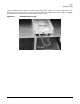
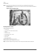
Step 5. Determine how each cable will run from the ICE tray to its destination and secure them
appropriately. Figure 4-7 shows the rear ICE cables secured to the cable management hardware at
the back of the ICE.
Figure 4-7Securing REO Cables
Routing the XUC Cables
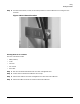
Cables connected to the XUC are:
• ICE 0/1 clocks
• ICE 2 clock (not all IOXs have three ICEs)
•GSP bus
• ICE 0,1,2 utilities
• Fan control for ICE 0, 1, and 2
•XUC DC power
•XPC control
• Rear display module
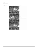
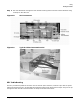
Figure 4-8 shows the connectors on the XUC.
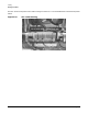
Figure 4-9 shows a typical configuration for the XUC.
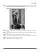
Step 1. Bundle all cables running to and from the XUC using tie wraps and/or VELCRO cable ties.