
Superdome Servers - I/O Expansion Cabinet Guide, Fifth Edition


Chapter 5
Adding an ICE to the IOX
Connecting the Cables
105
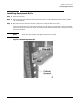
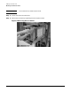
Figure 5-11 shows the location of connectors and mounting holes for cables to be attached in this procedure.
In the figure no tables are shown. The ICE, however, is shipped with tables identifying each connector.
Figure 5-11 ICE Connector Locations
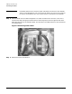
NOTE When viewed from the rear (as in Figure 5-11), the REO for XMIOB1 is on the left and the REO
for XMIOB3 is on the right. The REO cables cross over each other inside the ICE.
Connecting the REO Cables to ICE Backplane
IMPORTANT The ICE may ship with the REO cables already attached. If this is the case, skip this section.
This section describes how to connect the REO to the Superdome server. The section “Connecting the IOX to
the Superdome” on page 63 has additional information. It is recommended that you read that section first.
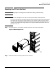
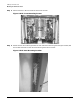
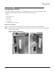
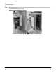
The REO cables are shipped with their ferrules attached at one end of the cable for mounting to the ICE. You
will pass the REO cables through the ferrule mounting holes and push the connectors onto the XMIOB
connectors.
Step 1. Locate the ends of the REO cables that has the ferrule attached.