
Superdome Servers - I/O Expansion Cabinet Guide, Fifth Edition


Chapter 5
Adding an ICE to the IOX
Connecting the Cables
108
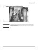
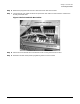
NOTE When viewed from the rear (as in Figure 5-14), the REO for XMIOB1 is on the left
and the REO for XMIOB3 is on the right. The REO cables cross over each other
inside the ICE.
Figure 5-14REO and Clock Connectors on the XMIOB
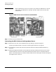
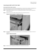
Step 6. Attach the strain relief bracket.
Connecting the REO Cables to the Superdome Server
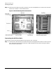
Step 1. Remove the rear door on the Superdome server by sliding it up off the hinge pins.
Follow the procedures found in the section “Removing Old Side Skins” on page 33.
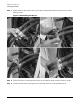
Step 2. Cut the green tie wraps and remove the green VELCRO ties holding the REO cables during
shipment.
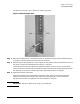
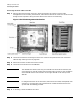
Step 3. Remove the appropriate R-PEC from the cable exit panel by loosening the two T15 Torx screws.
The REO cable pairs from the ICE mounted lowest should mount and run through the bottom
R-PEC in the cable exit panel. Likewise, the REO cables from the next higher ICE pass through the
next higher R-PEC, and so on.