
Superdome Servers - I/O Expansion Cabinet Guide, Fifth Edition


Chapter 5
Adding an ICE to the IOX
Connecting the Cables
109
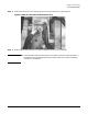
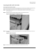
In Figure 5-15, the IOX is not in place for illustrative purposes.
Figure 5-15Removing R-PEC
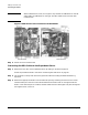
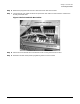
Step 4. Determine the destination to the Superdome server of the REO cable and pass the REO cable pair
through the cable exit panel where the R-PEC was removed.
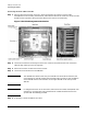
Step 5. Determine which shield protector to remove (green or blue) and pull the perforated section. Discard
the plastic. The shield is exposed after the protector is removed.
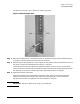
Use the blue section when the destination Superdome cabinet is next to the IOX. Use the green
section when there is another cabinet between the IOX and the destination Superdome cabinet. See
the discussion in the section “Connecting the REO and GSP Bus Cables” on page 64.
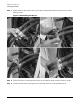
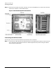
Step 6. Separate the halves of an R-PEC.
The R-PEC attaches to the exposed shield in the REO cable. There are two halves that fasten
together with three T15 Torx screws. REO cables are always attached in pairs. Each R-PEC,
therefore, has two holes. Unused R-PECs must have blanks in the holes.
IMPORTANT The R-PEC blanks must occupy all unused holes.