
Superdome Servers - I/O Expansion Cabinet Guide, Fifth Edition


Chapter 5
Adding an ICE to the IOX
Connecting the Cables
114
Connecting the Clock Cable to the ICE
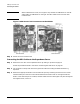
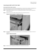
Step 1. Pass the cable from the back of the XUC, down the nearest rack channel, over the cable
management arm of the newly installed ICE, and under the cable strain relief arm. Be sure to add
enough service loop when routing the clock cable to allow the ICE to extend fully.
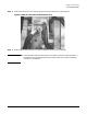
Figure 5-22Cable Management Mechanism
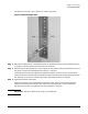
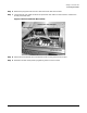
Step 2. Locate the clock ferrule mounting hole at the rear of the ICE and pass the two clock connectors
cable through. See Figure 5-11 on page 105.
Step 3. Secure the clock ferrule with two T20 Torx screws.
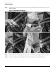
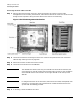
Step 4. Locate the clock connectors on the XMIOBs.
NOTE The XMIOBs are identical, but they are inverted from one another. Therefore, the
clock connector on the left (looking from the back side if the ICE) is near the bottom
of the XMIOB and the clock connector on the right XMIOB is near the top of the
XMIOB.
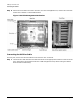
NOTE In configurations with one or three ICEs, there will be an unused, and exposed, clock
connector in one clock cable. This unused section of cable should be stored in the
zip-lock EMI shielded bag provided.
Step 5. If necessary, remove the REO strain relief.