
Superdome Servers - I/O Expansion Cabinet Guide, Fifth Edition


Chapter 5
Adding an ICE to the IOX
Connecting the Cables
119
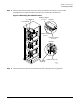
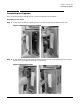
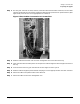
Step 2. Pass the cable from the back of the XUC, down the nearest rack channel, over the cable
management arm, under the strain relief arm of the newly installed ICE. Be sure to add enough
service loop when routing the cable to allow the ICE to extend fully.
Figure 5-27Routing Fan Control Cable
Step 3. Locate the fan control connector on the back of the ICE. See Figure 5-11 on page 105.
Step 4. Secure the connector by tightening the two captive cable connector screws. Secure the cable to the
strain relief arm, the roller management arm, and the rear of the ICE chassis at the Tee-bar or
cable bundle bracket.
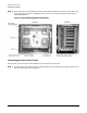
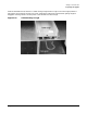
Connecting the ICE DC Power Cable
For every ICE, there is one power cable that runs from the XPC to the ICE.
Step 1. Locate the XPC end of the power cable and connect to the appropriate connector on the rear of the
ICE. See Figure 5-20 on page 112.
4/13/01
60IOX062
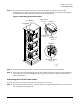
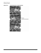
See Detail A
Detail A
Detail B
I/O Bay 0 Fan
To Ice 1
I/O Bay Fan Control
(Typical)
To Ice 2
I/O Bay 0 Fan
See Detail B
To Ice 0
I/O Bay 0 Fan