
Superdome Servers - I/O Expansion Cabinet Guide, Fifth Edition


Chapter 6
Remove and Replace Procedures
Removing the ICE
137
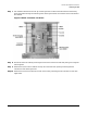
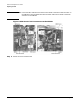
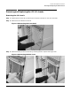
Step 7. Pull the REO cables from the ICE by removing the four screws around each ferrule and then by
pulling the cable through the mounting holes. See Figure 6-10 for the locations of the ICE cables to
be removed.
Figure 6-10ICE Connector Locations
Step 8. Disconnect the clock cable by removing the screw around its ferrule and then pulling it through the
mounting hole.
Step 9. Remove the I/O fan control cable at the top rear of the ICE back panel by loosening the two
connector screws. See Figure 6-10.
Step 10. Remove the I/O Utilities Cable at the rear of the ICE by loosening the two connector screws. See
Figure 6-10.