
Superdome Servers - I/O Expansion Cabinet Guide, Fifth Edition


Chapter 6
Remove and Replace Procedures
Replacing the ICE
141
Replacing the ICE
Follow the procedures in the section “Mounting the ICE into the Rack” on page 99 and mount the ICE into the
cabinet.
WARNING Use two people or a lifting device as the unit is bulky as well as heavy.
Connecting the Cables
Step 1. Locate the ends of the REO cables that has the ferrule attached.
NOTE Each REO cable has two connectors (input and output) that attach to each XMIOB.
There are two XMIOBs per ICE, one for each I/O chassis, but you may only have one
I/O chassis, and therefore, will only connect one pair of connectors to one XMIOB.
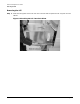
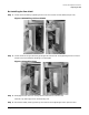
Step 2. Pass the cables over the cable management arm, under the cable strain relief arm, and run the
connectors through the appropriate REO ferrule mounting hole(s).
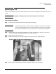
Step 3. Remove the strain relief bracket.
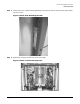
Step 4. Push the ferrule(s) up to the mounting hole(s) and secure with four screws supplied.
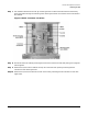
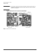
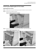
Figure 6-14REO Cable Ferrule Mounted in ICE
Step 5. Push the REO cable connectors into their respective connectors on the XMIOB.