
Superdome Servers - I/O Expansion Cabinet Guide, Fifth Edition

Chapter 6
Remove and Replace Procedures
Removing and Replacing the ICE I/O chassis
147
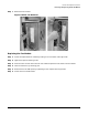
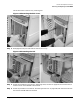
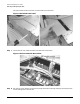
Step 6. Remove the I/O chassis by loosening its retaining screws and pulling it out of the ICE.
Figure 6-21Removing the I/O Chassis
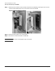
Step 7. Place the I/O chassis on an approved ESD work space and remove each PCI controller cards.
IMPORTANT Mark each card so that you will remember the slot locations.
Replacing the I/O Chassis
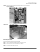
Step 1. Re-install all previously removed PCI controller cards in the I/O chassis.
Step 2. Re-install the I/O chassis lid.
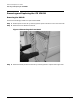
Step 3. Install the replacement chassis by sliding it along the center separator wall until the guide pins
engage and the connectors seat.
Step 4. Tighten the captive screws.
Step 5. Attach all the external I/O cables that were previously connected to the chassis.
Step 6. Install the ICE EMI panel.
Step 7. Deactivate the slide locks and push the ICE tray into the rack
Step 8. Lock the tray retaining pins
Step 9. Re-install the EMI panel by pressing it onto the ICE and tightening the four captive screws.
Step 10. Replace the front cosmetic panel.