
Superdome Servers - I/O Expansion Cabinet Guide, Fifth Edition


Chapter 6
Remove and Replace Procedures
Removing and Replacing the XUC
157
Step 9. Pull the GPS bus cable from the XUC through the ferrule mounting hole by removing the two
screws holding the cable ferrules.
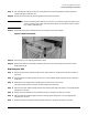
Step 10. Disconnect and remove all remaining cables on the back of the XUC.
IMPORTANT Be sure to identify each cable as you remove it. To make sure you put it back on the
correct connector later, mark each cable with tape or by some other means so that it
may readily identified later.
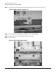
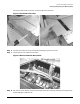
Step 11. Press both slide locks to release the XUC and remove it from IOX cabinet.
Figure 6-32XUC Extended
Step 12. Place the XUC on an ESD approved work space.
Step 13. Remove the slide rails attached to the sides of the XUC by removing the two T20 Torx screws
holding each slide.
Replacing the XUC
Step 1. Attach the previously removed slides on each side of the XUC using the two T20 Torx screws on
each side.
Step 2. Carefully place the mating slides on the XUC into the cabinet slides and push the XUC until the
slides lock.
Step 3. Remove the XUC side panel by loosening the six captive T10 Torx screws.
This panel allows access to the ICE clock and GSP bus connections.
Step 4. Pass the ICE clock cables through the ferrule mounting hole and press them in to the appropriate
connectors in the XUC.
Step 5. Attach the clock cable ferrule to the back of the XUC using the two T10 Torx screws.
Step 6. Pass the GSP bus cable through the ferrule mounting hole and press it in to the appropriate
connectors in the XUC.
Step 7. Attach the GSP bus cable ferrule to the back of the XUC using the two T10 Torx screws.