
Superdome Servers - I/O Expansion Cabinet Guide, Fifth Edition


Chapter 6
Remove and Replace Procedures
Removing and Replacing the PM/CLU (UGUY)
164
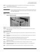
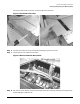
Step 9. Unlock the cover and move up the CPA bezel up.
Step 10. Lower the EMI cover as shown in Figure 6-39.
Step 11. Remove the PM/CLU using the ejector mechanism.
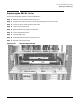
Figure 6-39 PM/CLU Replacement
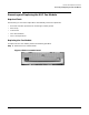
Replacing the PM/CLU
To replace the PM/CLU, preform the following steps:
Step 1. Connect your ESD wrist strap to the ESD grounding lug on the XUC door.
Step 2. Install the replacement PM/CLU board.
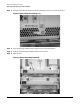
Step 3. Set the cabinet number to appropriate value (8 or 9).
Step 4. Attach the clock cable ferrule to the back of the XUC using the two T10 Torx screws.
Step 5. Re-attach the XUC side panel by tightening the six T10 Torx screws
Step 6. Press the slide locks to release the slides and push the XUC into the rack.
Step 7. Close the front EMI cover.
Step 8. Slide down the CPA bezel and lock the cover.
Step 9. Disconnect you ESD strap.
Step 10. Replace the cosmetic bezel.
Step 11. Re-connect the AC power cord to the XPC.
Step 12. Switch on the IOX power.