
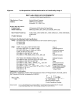
Superdome Servers - I/O Expansion Cabinet Guide, Fifth Edition


Chapter 1
Introduction
Overview
4
ICE
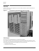
The ICE supports a maximum of two 12-slot I/O chassis. Each I/O chassis interfaces with an I/O Expansion
Master I/O backplane (XMIOB) contained within an EMI enclosure and installed on the ICE tray.
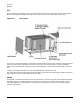
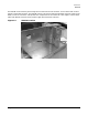
Figure 1-3 ICE Layout
The ICE I/O tray slides forward out of the cabinet to allow access to the PCI slots. Cables are routed out of the
front of the I/O chassis, underneath the chassis, and out the rear of the enclosure. A cable management
system at the rear of the ICE provides the service loop necessary to allow the forward movement of the ICE
tray.
Cooling is provided by redundant (N+1=4), hot-swappable fans located in the rear.
The ICE chassis external dimensions (excluding cosmetic panels and mounting flanges) are 394 mm (15.51 in)
high X 448 mm (17.64 in) wide X 948 mm (37.3 in) deep.
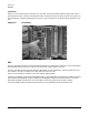
XMIOB
The XMIOB is a connector board for one 12-slot I/O chassis. It connects to the I/O chassis backplane (HIOB).
XMIOBs exist in pairs, supporting two 12-slot chassis in a single ICE: Chassis 1 and Chassis 3. They are
connected together by a bridge cable. For architectural reasons, the two I/O chassis are distinguished as
chassis 1 and chassis 3.