
Superdome Servers - I/O Expansion Cabinet Guide, Fifth Edition

Chapter 1
Introduction
Overview
10
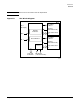
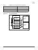
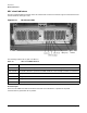
Additionally, each BPS accepts and generates control I/O interface signals from/to the Power Monitor
Subsystem (PM3) assembly, which monitors and controls the power system. The PM3 detects the number and
type of BPS modules present. If any of these modules fails, the PM3 may shut down the system dependent on
the specific anomaly. The PM3 controls the On/Off status of the XPC +48Vdc rail.
Figure 1-9 BPS Functional Diagram
The I/O expansion cabinet requires a single phase 220 VAC input. Each BPS has push-button resetable
breakers located above each AC power input connector.
Table 1-2 lists the AC power requirements for the I/O expansion cabinet.
Table 1-2 I/O Expansion Cabinet Power Requirements
Requirements Value
Nominal input voltage 200-240 (VAC rms)
Input voltage range (minimum-maximum) 176-264 (VAC rms)
Frequency range (minimum-maximum) 47-63 (Hz)
Number of phases 1
Marked Electrical input current 16A @ 200 VAC
20A @ 176 VAC
Maximum inrush current 90 max (A peak)
Power factor correction 0.95 minimum
5/14/01
60IOX025
Bulk Power Supply BPS
Single Phase
AC Input
No. 0
Input Filter
Rectifier
Power Factor
Correction
Single Phase
No. 1
AC Input
Input Filter
Rectifier
Power Factor
Correction
BPS Logic
and Control
48 VDC
Converter
Converter
5 VDC
Converter
5 VDC
Converter
48 VDC
I C I/O
and Control
I/O
Output Filter
Isolation Diodes
5 VDC
48 VDC
2