
Superdome Servers - I/O Expansion Cabinet Guide, Fifth Edition


Chapter 1
Introduction
System Configurations
23
System Configurations
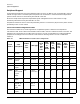
The allowed combinations of cabinet sizes, I/O chassis, slot totals, and free space for mounting other
peripherals are summarized in Table 1-7.
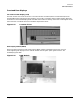
CAUTION Do not use the top 8U of the 1.96-meter cabinet to mount IOX components.
When configuring multiple Superdome and IOX cabinets, certain guidelines must be followed. Full I/O
support of a Superdome 64 Way requires eight additional I/O connections. Therefore, two IOX cabinets are
required. The IOX may be loaded with two ICEs in each IOX or three ICEs in one IOX with one ICE in the
other IOX. Each IOX must have its own XUC and XPC.
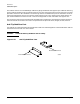
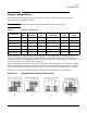
REO Cabling between HD and IOX can cross only one additional cabinet. Therefore, in a Superdome 64 Way
with two IOX (Figure 1-21), the far right server cabinet can not be connected to the far left IOX. In the figure,
solid lines represent REO cables. Configurations (a), (b), and (c) are legal; while configuration (d) is illegal.
Figure 1-21 illustrates the allowable configurations between the Superdome server and the IOX.
Figure 1-21 Allowable Multi-Cabinet Configurations
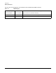
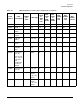
Table 1-7 Allowable Configurations
Cabinet Size
XPC
(pwr)
XUC
(utilities)
12-slot
ICE
Total number of
I/O chassis
Total #
slots
Free Rack
Space
33 U (1.61m) 1 1 1 2 24 18 U
33 U (1.61m) 1 1 2 4 48 9 U
33 U (1.61m) 1 1 3 6 72 0 U
41 U (1.96m) 1 1 1 2 24 26 U
41 U (1.96m) 1 1 2 4 48 17 U
41 U (1.96m) 1 1 3 6 72 8 U