
Superdome Servers - I/O Expansion Cabinet Guide, Fifth Edition

Chapter 3
Installing the IOX
Connecting the IOX to the Superdome
67
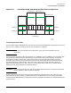
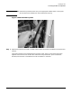
Figure 3-29 Superdome 64 Way with Balanced IOX Cabinet Configuration
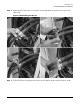
Connecting the REO Cables
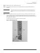
The following procedure describes how to connect and route an REO cable between the Superdome server and
the IOX. This is a generic procedure, because each configuration is different.
NOTE Insure that you understand the configuration of your particular Superdome and IOX
installation.
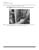
The terminations of the REO cables are identified: CPU CABINET and IOX CABINET. Also each REO cable
has two sections where the shield is exposed. Each of these sections has a plastic protector covering the
shield. Before installing a REO cable, remove these protectors by pulling the perforated sections and
discarding. The protection must be removed to allow electrical contact between the shield and the R-PEC.
One shield section has a blue protector and the other has a green one. Use the blue section when the
destination Superdome cabinet is next to the IOX. Use the green section when there is another cabinet
between the IOX and the destination Superdome cabinet.
IMPORTANT Remove the protective plastic only on the appropriate shield section. Leaving the other shield
section exposed can cause inadvertent shorting.
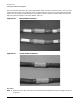
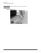
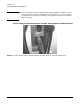
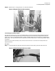
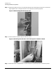
Figure 3-30 shows the blue plastic shield protectors nearest the Superdome server end, and Figure 3-31
shows the green protectors. When it is determined how far the REO cable has to run and where it passes
through the Superdome bulkhead, the appropriate shield is exposed and secured to the Superdome bulkhead
using an R-PEC.
60IO890a
04/11/00
0
0
1
1
0
0
0
0
2
2
Chassis Slots
Chassis Slots
Chassis Slots
Chassis Slots
Front View
(I/O Bays 0)
I/O Bay 1
I/O Bay 1
I/O Bay 0
I/O Bay 0
SPU Cab (n)
SPU Cab (n+1)
IOX Cab (n+8)
IOX Cab (n+9)
3
3
1
1
1
1