
Superdome Servers - I/O Expansion Cabinet Guide, Fifth Edition


Chapter 4
Cabling
Cable Management
84
Cable Management
The IOX provides a large amount of additional I/O for the Superdome systems. The number and weight of the
cables within the IOX is large. Cable management hardware is provided at several points in the ICE.
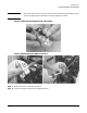
• A wire former (or “potato masher”) provides strain relief for external I/O cables at the front of the I/O
chassis. The cables are tied to this former.
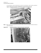
• The cables are routed to the back of the ICE in a space between the I/O chassis and the ICE tray. At the
back of the ICE tray, these external cables are secured to a cable bundle bracket at the rear of the ICE
tray. See Figure 4-1.
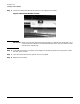
• The roller at the apex of the cable management system provides strain relief and controls the bend radius
of the cables It also folds them into a compact space. Most of the service loop required to extend the shelf
is implemented by routing the cables over the roller cable management arm assembly.
• Additional service loop is obtained by looping the cable bundle off the roller in a “C” shape. A special
“teebar” bracket mounted at the rear of the ICE provides strain relief. This bracket assembly clamps the
bundle to prevent cables from slipping down and service loop being lost.
• After exiting the ICE, the cables are routed down channels in the sides of the rear cabinet extensions and
held in place with channel brackets. In addition to the channel brackets there are rectangular holes in the
channel for securing cable ties. Square holes are located along the channel for snapping in cable tie
anchors. Tie wraps may be looped through these anchors.
• Internal cables coming from the back of the ICE are secured to the strain relief arm. See Figure 4-1
• The REO and clock cables are routed through an EMI enclosure and connected to the XMIOB. REO and
clock cable shield termination is accomplished by the cable ferrule/EMI Level 2 interface.