32/64/76-Slot, 5.2 Gbyte-Drive Optical Jukebox Upgrade and Conversion Instructions Edition 1 Part No.
Printing History New editions of these instructions incorporate all material updated since the previous edition. The printing date and part number indicate the current edition. The printing date changes when a new edition is printed. (Minor corrections and updates incorporated at reprint do not change this date.
Typographical Conventions The following typographical conventions are used in these instructions: Emphasis: Denotes important information. Keycap: Keys on the library. Computer Output: Information displayed in the display window and screen menu items that you can select. WARNING Warnings call attention to a procedure or practice that could result in personal injury if not correctly performed. Do not proceed until you fully understand and meet the required conditions.
These Instructions These upgrade/conversion instructions include the following topics: Chapter 1 Checking the parts in your kit against the parts list. Checking that you have the correct tools. Checking that you have the most current firmware for the jukebox controller and the drives. Chapter 2 Procedures for adding two drives to a two-drive 5.2-Gbyte-drive jukebox and enabling 32 additional cartridge slots. Chapter 3 Procedures for converting two- or four-drive 2.
1 First Steps 1-1
First Steps Overview Overview This chapter provides the following: • Contents of each upgrade and conversion kit • A checklist of equipment, tools, and firmware needed 1-2
First Steps Upgrades, Conversions, and Kit Contents Upgrades, Conversions, and Kit Contents These instructions explain how to install upgrade/conversion kits for the following product configurations. NOTE • Adding two drives to a two-drive 5.2-Gbyte-drive jukebox and enabling 32 additional cartridge slots. • Converting a two-drive 2.6-Gbyte-drive jukebox to a two-drive 5.2-Gbyte-drive jukebox and adding 32 additional cartridge slots (not activated). • Converting a four-drive, 64-slot 2.
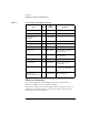
First Steps Upgrades, Conversions, and Kit Contents Table 1-1 Contents of the C1155J/K/L Upgrade Kits Qty Part Number 5.
First Steps Upgrades, Conversions, and Kit Contents All jukeboxes of the 5.2-Gbyte generation are shipped with a full complement of 64 cartridge slots. In addition to converting the drive technology to 5.2 Gbyte capacity, the conversion kits also provide the capability to add 32 cartridge slots to 32-slot jukeboxes. By adding slots, the jukebox matches the configuration of the jukebox as shipped from the factory and prepares the jukebox to upgrade to a four-drive 5.2 Gbyte drive jukebox later.
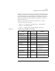
First Steps Upgrades, Conversions, and Kit Contents Qty Part Number left panel - parchment white 1 C5175-00203 right panel - parchment white 1 C5175-00205 product label 1 5181-9902 placed over the current product label 160ex nameplate 1 C1150-84303 C5131J kit only Part Comments or User Guide 1 C1150-84304 C5131K and C5131L option #726 C1160-90015 C5131J kit only or C1160-90016 or Table 1-3 C5131K and C5131L #726 kits only C1160-90017 C5131L #700 and #768 kits only User Guide,
First Steps Upgrades, Conversions, and Kit Contents Part Part Number Qty Comments RFI clamp 2 869623 two plates, two end clips EMI gasket 1 C1160-80602 T-20 screws 6 0515-2282 extra assembly and panel mounting screws M3x6 T-10 screws 32 0515-2382 for mounting drives in the drive enclosure flat cable clamp 2 1400-0514 left panel - flint grey 1 C5175-00202 C5132J & C5131L options #700 & 726 right panel - flint grey 1 C5175-00204 C5132J & C5131L options #700 & 726 left panel - pa
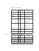
First Steps Upgrades, Conversions, and Kit Contents Part User Guide Qty Part Number 1 C1160-90015 Comments C1132J kit only or C1160-90016 or Table 1-4 C5132K and C5132L option #726 kits only C1160-90017 C5132L #700 and #768 kits only User Guide, localized CD ROM 1 C1160-90001 C5132J kit only Upgrade and Conversion Instructions 1 C1160-90018 These instructions. Contents of the C5133J/L Conversion Kits Qty Part Number 5.
First Steps Upgrades, Conversions, and Kit Contents Qty Part Number right panel - flint grey 1 C5175-00204 C5132J & C5131L #700 & 726 kits only left panel - parch.
First Steps Equipment, Tools, and Firmware Needed Equipment, Tools, and Firmware Needed PC Tool Equipment and Software Needed When upgrading or converting the library you will be connecting your PC tool to the jukebox for two reasons: downloading firmware to the jukebox controller and drives and verifying proper operation of the drives after installation.
First Steps Equipment, Tools, and Firmware Needed Tools Required • T-10 and T-20 Torx® drivers Firmware Needed Before beginning an upgrade or conversion, obtain the most current version of the jukebox controller and drive firmware for the model and option of the jukebox you are upgrading/converting. Firmware for all models and options of this jukebox is available for download at: www.hp.com/isgupport/optical/fw/firmware.html.
First Steps Equipment, Tools, and Firmware Needed 1-12
2 Upgrading Drives and Capacity in 5.
Upgrading Drives and Capacity in 5.2 Gb Drive Jukeboxes Before You Begin Before You Begin Check the kit contents, tools and equipment needed for this upgrade in Chapter 1. IMPORTANT Before you begin, make sure you have the most current firmware for the jukebox controller and the drives for the model and option jukebox you are upgrading. Firmware may be obtained at www.hp.com/isgsupport/optical/firmware.html.
Upgrading Drives and Capacity in 5.2 Gb Drive Jukeboxes Remove the Right and Left Access Panels Remove the Right and Left Access Panels WARNING Disconnect the power cord before taking the jukebox apart to prevent possible electrical shock. CAUTION Do not switch off power to the jukebox until you are sure the SCSI bus is inactive. Switching off the jukebox when the SCSI bus is active can cause data loss and/or indeterminate bus states. 1. Turn power off.
Upgrading Drives and Capacity in 5.
Upgrading Drives and Capacity in 5.2 Gb Drive Jukeboxes Add Drives Add Drives 1. Disconnect all cables from the currently installed drives to the interposer PCA. 2. Remove the two T-20 screws securing the empty drive location cover plate ( # 1 on Figure 2-2).
Upgrading Drives and Capacity in 5.2 Gb Drive Jukeboxes Add Drives 3. Mount the two new drives into the two drive enclosures supplied in the kit. a. Remove the adhesive backing on the plastic cable clamp and mount the clamp at the position shown in #1 on Figure 2-4. b. Remove the top and bottom cable access panels on the drive enclosure. Two T-10 screws hold each plate (see #1 on Figure 2-4). Figure 2-3 Removing Top and Bottom Cable Access Panels c.
Upgrading Drives and Capacity in 5.2 Gb Drive Jukeboxes Add Drives Figure 2-4 Inserting a Drive Into a Drive Enclosure and Connecting Drive Cables d. As you connect the drive interface cables into their connectors on the rear of the drive, slide the cables into the cable clamps. e. Mount the drive in the enclosure with four T-10 screws f. Replace the top and bottom cable access panels. Secure them with two T-10 screws apiece.
Upgrading Drives and Capacity in 5.2 Gb Drive Jukeboxes Add Drives Figure 2-5 Mounting the Drive Into the Enclosure g. Slide the enclosure into the chassis and secure the enclosure to the chassis with one T-20 screw. 4. Repeat Step 3 a to g for the second drive. 5. For all drives, connect the drive cables to the interposer PCA (see Figure 2-6). NOTE • SCSI cable (#1) • drive interface cable (#2 ) • drive fan power cable (#3 ) • drive power cable (#3) Connect the drive power cable last.
Upgrading Drives and Capacity in 5.
Upgrading Drives and Capacity in 5.2 Gb Drive Jukeboxes Mount the Configuration Module Mount the Configuration Module Insert the configuration module into the connector on the interposer PCA as shown in the figure below. Figure 2-7 Mounting the Configuration Module Go to Chapter 4, “Downloading Firmware.
3 Converting 2.6 Gb Drive Jukeboxes to 5.
Converting 2.6 Gb Drive Jukeboxes to 5.2 Gb Drive Jukeboxes Before You Begin Before You Begin Check the kit contents, tools and equipment needed for this conversion in Chapter 1 IMPORTANT Before you begin, make sure you have the most current firmware for the jukebox controller and the drives for the model and option jukebox you are converting. Firmware may be obtained at www.hp.com/isgsupport/optical/firmware.html.
Converting 2.6 Gb Drive Jukeboxes to 5.2 Gb Drive Jukeboxes Conversions Conversions 1. If jukebox is not on, turn it on. 2. Ensure that there are no disks in the drives. Execute EMPTY DRIVES from the control panel TEST * menu, if necessary. IMPORTANT Record the jukebox configuration settings so that the settings may be restored after the conversion. 3. Record the jukebox configuration settings using the CONF * menu.
Converting 2.6 Gb Drive Jukeboxes to 5.2 Gb Drive Jukeboxes Remove the Right, Left and Rear Panels Remove the Right, Left and Rear Panels WARNING Disconnect the power cord before taking the jukebox apart to prevent possible electrical shock. 1. Remove the right-side, left-side, and rear panels.
Converting 2.6 Gb Drive Jukeboxes to 5.2 Gb Drive Jukeboxes Remove the Right, Left and Rear Panels 2. Disconnect the control panel and power cable to prepare the right front panel for removal a. Remove the control panel cover plate (#1). b. Remove the control panel interface cable and power cable from the control panel PCA (#2 and #3). c. Rotate the control panel until the display faces the right end of the jukebox (see #1 on Figure 3-3).
Converting 2.6 Gb Drive Jukeboxes to 5.2 Gb Drive Jukeboxes Remove the Right, Left and Rear Panels 3. Remove the screws that mount the right front panel (see Figure 3-3). Remove the two screws on the top and bottom rear of the panel and the bottom front of the panel (see screws labeled #2 on the left and right of Figure 3-3) 4. Remove the T-20 screw located under the rear edge of the top plastic center cover (#5 on Figure 3-3). 5.
Converting 2.6 Gb Drive Jukeboxes to 5.2 Gb Drive Jukeboxes Install a New Interposer PCA and Add the Configuration Module Install a New Interposer PCA and Add the Configuration Module 1. Remove all drive cables and jukebox cables from the interposer PCA (see Figure 3-4). 2. Remove the six T-20 screws holding the PCA to the chassis. Remove the PCA (see arrows on Figure 3-4). Figure 3-4 Disconnecting Cables and Screws 3. Mount the interposer PCA from the kit. 4.
Converting 2.6 Gb Drive Jukeboxes to 5.2 Gb Drive Jukeboxes Install a New Interposer PCA and Add the Configuration Module • #4 - GPIO cable • #5 - power input and fan sense cables • #6 - vertical-path-clear emitter cable IF INSTALLING A C5132J/K/L KIT OR C5133J/K/L KIT CONTINUE WITH STEP 5 AND INSTALL A CONFIGURATION MODULE. IF INSTALLING A C5131J/K/L KIT GO TO THE NEXT PROCEDURE. 5. Mount the configuration module as shown in Figure 3-5 (into socket shown by #1 on Figure 3-4). 6.
Converting 2.6 Gb Drive Jukeboxes to 5.2 Gb Drive Jukeboxes Replace 2.3 Gb Drives With 5.2 Gb Drives Replace 2.3 Gb Drives With 5.2 Gb Drives 1. Remove all drive cables from the interposer PCA for all installed drives (see Figure 3-6). • #1 - drive fan power cable • #2 - SCSI cable • #3 - drive interface cable • #4 - drive power cable (two connectors) This same pattern of cables on the interposer PCA is the same for each drive. 2.
Converting 2.6 Gb Drive Jukeboxes to 5.2 Gb Drive Jukeboxes Replace 2.3 Gb Drives With 5.2 Gb Drives Figure 3-7 Removing the Drive Cables 4. Disconnect the drive cables from the rear of the drive (see Figure 3-7). • #2 - drive interface cable • #3 - SCSI cable • #4 - drive power cable 5. Remove the four T-10 screws that hold the drive in the drive enclosure (see Figure 3-8) and slide the drive out of the enclosure. Repeat for each drive.
Converting 2.6 Gb Drive Jukeboxes to 5.2 Gb Drive Jukeboxes Replace 2.3 Gb Drives With 5.2 Gb Drives Figure 3-8 Removing the Drive From the Drive Enclosure 6. Mount a new drive into the drive enclosure. a. Place the new drive into the enclosure at the top position (see Figure 3-7). Secure with two T-10 screws on each side. b. Remove the adhesive backing on the plastic cable clamp and position the clamp on the rear of the drive as shown in #1 on Figure 3-7. c.
Converting 2.6 Gb Drive Jukeboxes to 5.2 Gb Drive Jukeboxes Replace 2.3 Gb Drives With 5.2 Gb Drives Figure 3-9 Connecting Drive Cables to the Interposer PCA 7. Connect the drive cables to the interposer PCA for each drive (see Figure 3-9). • #1 - drive fan power cable • #2 - SCSI cable • #3 - drive interface cable • #4 - drive power cable (two connectors) This same pattern of cables on the interposer PCA is the same for each drive. 8. Go to Install the Replacement Interface PCA on the next page.
Converting 2.6 Gb Drive Jukeboxes to 5.2 Gb Drive Jukeboxes Install the Replacement Interface PCA Install the Replacement Interface PCA NOTE Note the interface cable configuration and the selection on the interface select switch so the same configuration can be restored after replacing the interface PCA. 1. Remove the SCSI cables and power cable from the interface module. 2. Remove the four T-20 screws securing the interface module to the side of the chassis (see Figure 3-10). 3.
Converting 2.6 Gb Drive Jukeboxes to 5.2 Gb Drive Jukeboxes Install the Replacement Interface PCA 4. Remove the eight T-15 PCA screws and remove the PCA (see Figure 3-11). 5. Mount the replacement interface PCA.
Converting 2.6 Gb Drive Jukeboxes to 5.2 Gb Drive Jukeboxes Install the Replacement Interface PCA 6. Connect the power and SCSI cables to the interface PCA (see #1, #2, and #4 on Figure 3-12). 7. Remount the interface module on the side of the chassis with four T-20 screws (see Figure 3-10). Figure 3-12 Mounting the SCSI Interface Cables 8. If installing kit C5131J/K/L, go to “Add Cartridge Magazines (C5131J/K/L Kits Only)” on page 3-16.
Converting 2.6 Gb Drive Jukeboxes to 5.2 Gb Drive Jukeboxes Add Cartridge Magazines (C5131J/K/L Kits Only) Add Cartridge Magazines (C5131J/K/L Kits Only) CAUTION When adding magazines into the chassis, do not move the customer’s disks from the their current locations. If the event that you must move a cartridge, record the cartridge location and orientation so the cartridge can be replaced to its original position later. 1. Clip the cartridge magazines into the area shown in Figure 3-13. a.
Converting 2.6 Gb Drive Jukeboxes to 5.2 Gb Drive Jukeboxes Add Cartridge Magazines (C5131J/K/L Kits Only) Figure 3-13 Adding Cartridge Magazines 4. Go to “RFI Modifications (For Conversions)” on the next page.
Converting 2.6 Gb Drive Jukeboxes to 5.2 Gb Drive Jukeboxes RFI Modifications (For Conversions) RFI Modifications (For Conversions) Mounting RFI Clamps on the SCSI and GPIO Cables 1. Mount the RFI clamp on the SCSI and GPO cables on the left side of the interposer PCA. Figure 3-14 Adding an RFI Clamp to the SCSI and GPIO Cables Near the Interposer PCA a. Clip on end of the two RFI plates together (#1 on Figure 3-14). b. Place the clamp over BOTH SCSI and GPIO cables. c.
Converting 2.6 Gb Drive Jukeboxes to 5.2 Gb Drive Jukeboxes RFI Modifications (For Conversions) 2. Attach double-sided tape pads to the ends of the two thin RFI clamps. Figure 3-15 Adding RFI Clamps to the SCSI and GPIO Cables Down the Front Side 3. Press the SCSI and GPIO cables against the side of the chassis and mount the two RFI clamps in the positions shown in Figure 3-15. IMPORTANT RFI suppression is only accomplished if the SCSI/GPIO cable bundle is strapped tightly to the side of the chassis.
Converting 2.6 Gb Drive Jukeboxes to 5.2 Gb Drive Jukeboxes RFI Modifications (For Conversions) Adding an RFI Cabinet Strip NOTE You may apply the EMI gasket to the front panel either before or after you remount the front panel on the jukebox. 1. Remove the adhesive backing on the EMI gasket. 2. Stick the EMI gasket to the center of the bottom edge of the front panel as shown on the left of Figure 3-16). IMPORTANT Figure 3-16 Note the orientation of the EMI gasket in the insert on Figure 3-16.
Converting 2.6 Gb Drive Jukeboxes to 5.2 Gb Drive Jukeboxes RFI Modifications (For Conversions) CAUTION As you remount the right front panel in the next steps, be careful as you lower the control panel assembly through the hole in the top of the chassis. Make sure the display faces the mailslot end of the panel and that you do not catch the control panel PCA on the edge of the chassis as you lower the panel onto the chassis. 3. Remount the right front panel. a.
Converting 2.6 Gb Drive Jukeboxes to 5.
4 Downloading Firmware
Downloading Firmware Overview Overview This chapter provides the following: • Procedures for checking the revision level of the jukebox and drive firmware. • Procedures for connecting to the jukebox for downloading firmware.
Downloading Firmware Checking and Downloading Firmware Checking and Downloading Firmware NOTE If upgrading a jukebox: 1. Go to “Check the Firmware Revision Level” to see if the jukebox controller and/or drives need the current revision of firmware. 2. Go to “Downloading Firmware” if necessary. If converting a 2.6-GB-drive jukebox: 1. Go to “Downloading Firmware” and download the current revision of jukebox controller firmware. 2.
Downloading Firmware Checking and Downloading Firmware Downloading Firmware NOTE Ensure that the jukebox is not in LUN mode (logical unit numbering). Downloads must be done with LUN mode off. IMPORTANT If you are going to download firmware for the jukebox controller, the customer’s default configurations should be recorded so that the jukebox can be correctly restored. Go to the CONF * menu on the control panel to access and display the current jukebox configurations. 1. Turn the jukebox off. 2.
5 Verifying Jukebox Operation, Labeling, and Cleanup
Verifying Jukebox Operation, Labeling, and Cleanup Verify Proper Jukebox Operation Verify Proper Jukebox Operation 1. Check for proper drive operation. Run a “random write and verify” for approximately two minutes to check the operation of the drive. 2. Check for proper jukebox operation by running the “Wellnes Test.” NOTE If a failure occurs, refer to Chapter 4, Troubleshooting” in the 160ex/320ex/400ex Optical Jukebox Service Manual (C1160-90030). 3.
Verifying Jukebox Operation, Labeling, and Cleanup Restore Interface Selection and Cabling Restore Interface Selection and Cabling 1. Replace the SCSI cables on the interface PCA ports in the same configuration as they were before the upgrade/conversion. 2. Place the interface select switch to select whichever interface type it was before the upgrade/conversion (single-ended or differential).
Verifying Jukebox Operation, Labeling, and Cleanup Restore Non-Default Configurations Restore Non-Default Configurations Table 5-1 Default Configuration Settings Configuration Default Value RECOVERY ON DUAL PICKER ON STARWARS ON SCSI LOG OFF SECURE OFF SECURE MAIL OUT POWER SECURE OFF REP RECOVERED ON CONF 40 OFF WRITE VERIFY ON LUN Mode OFF SCSI Addresses robotics controller = 6 drive 1 = 5 drive 2 = 4 drive 3 = 3 (if installed) drive 4 = 2 (if installed) Password 5-4 000-000-
Verifying Jukebox Operation, Labeling, and Cleanup Updating the Product Nameplate and Product Upgrade Label Updating the Product Nameplate and Product Upgrade Label 1. Place the product upgrade label partially over the product label as shown in Figure 5-1. DO NOT COVER THE SERIAL NUMBER.
Verifying Jukebox Operation, Labeling, and Cleanup Updating the Product Nameplate and Product Upgrade Label 2. Place the new product nameplate on the top of the jukebox as shown in Figure 5-2. Figure 5-2 Position of the Model Nameplate Replace the Jukebox Access Panels 1. If this is a conversion, use the left and right panels included in the kit. The replacement panels have cooling slots. 2. If removed the rear panel to add magazines, replace the rear panel.