
HP Surestore Bridge FC 2/1 LV and FC 4/1 HV Installation and Operations Guide


Chapter 1 Chapter Overview 17
Chapter 1
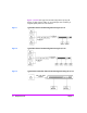
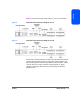
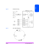
Figures 4 and 5 show the back panels of the 2/1 LV and 4/1 HV bridges.
Figure 4 Back Panel of the HP Surestore Bridge FC 2/1 LV
Figure 5 Back Panel of the HP Surestore Bridge FC 4/1 HV
SCSI and Fibre Channel connectors can be found on the back panel. Ethernet
and serial ports provide the means for configuration and management. The
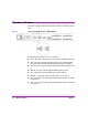
LED indicators (operation indicators) provide basic status information. A power
connector and power switch are located on the back panel. For proper
operation of the bridge, cable connections on the back panel should be
properly secured.