
HP Surestore Bridge FC 2/1 LV and FC 4/1 HV Installation and Operations Guide

Chapter 7 Switch Configuration 181
Chapter 7
Switch Configuration
HP/Brocade Switch and Fibre Channel Bridge Configuration
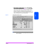
Use the default configuration for the Fibre Channel switch in SAN backup
configurations (see Figure 67 on page 166).
In this example the:
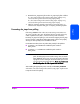
■ HP-UX host is attached to ports 1 & 2 of the switch
■ Windows NT server is attached to port 0
■ FC Bridge 4/1 HV is attached to port 6
Verify that the switch is not using Quick Loop mode.
Use zoning only if it is needed to simplify configuration on the hosts. See the
SAN Backup Solution Configuration Guide referenced at the end of this
chapter for more information.
Two changes should be made when connecting the Fibre Channel Bridge 4/1
HV or the 2/1 LV directly to a switch port.
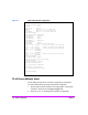
Use the bridge's Fibre Channel Configuration menu:
■ FC Port Mode to N_Port Mode
This provides a direct F_Port to N_Port connection between the switch and the
bridge.