
HP Surestore Bridge FC 2/1 LV and FC 4/1 HV Installation and Operations Guide


197
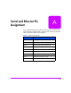
Serial and Ethernet Pin
Assignment
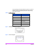
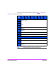
The pin assignments given for the DB-9 serial connection is in reference to the
serial receptacle on the back panel of the bridge. Use an RS-232 null modem
cable to connect the bridge to the host system.
Table 1 DB-9 Pin Assignments
Pin Number Function
Pin 1 No connection
Pin 2 Receive data to the Fibre bridge
Pin 3 Transmit data from the Fibre bridge
Pin 4 No connection
Pin 5 Ground
Pin 6 No connection
Pin 7 RTS (Request to Send), not used
Pin 8 CTS (Clear to Send), not used
Pin 9 No connection
A