
HP Surestore Bridge FC 2/1 LV and FC 4/1 HV Installation and Operations Guide


198 Appendix A
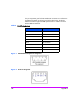
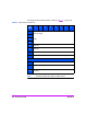
The pin assignments given for the RJ-45 Ethernet connection are in reference to
the Ethernet receptacle on the back panel of the Fibre bridge. The bridge
Ethernet connection supports the IEEE specifications for 10 Base-T and 100
Base-TX Ethernet standards.
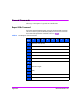
Figure 1 DB-9 Modular Receptacle Pin Assignment
Figure 2 RJ-45 Pin Assignment
Table 2 RJ-45 Pin Assignments
Pin Number Function
Pin 1 Transmit out +
Pin 2 Transmit out -
Pin 3 Receive in +
Pin 4 No connection
Pin 5 No connection
Pin 6 Receive in -
Pin 7 No connection
Pin 8 No connection