
HP Surestore Bridge FC 2/1 LV and FC 4/1 HV Installation and Operations Guide


42 Address Mapping Chapter 2
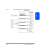
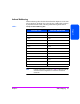
The indexed addressing table has the structure shown in Table 7 on page 41.
The bridge will allow up to 80 device entries to be mapped. The index table
can be manually edited and is then saved to the bridge FLASH memory. The
Configuration menu has options allowing the table to be filled in order of
increasing bus, target ID, or LUN, as may be desired for the specific
requirements needed.
Options are also provided to perform SCSI device discovery and fill the table
in the order that devices are discovered on a SCSI bus.
Indexed addressing mode is recommended for environments where SCSI
device configuration may change, and a fixed mapping from the application
to the target device is required. That is, if a SCSI device is removed from the
SCSI bus, and the bridge is power cycled, then the FC-to-SCSI addressing for
the remaining SCSI devices will not change and the SCSI devices can be
replaced at the same address. An example of such an environment is where
hot-pluggable devices may be used, thereby changing the order of devices on
a SCSI bus.
Auto Addressing
The auto addressing option is similar to indexed addressing. However, the
table used is created each time through SCSI device discovery upon power-up
(or other bridge initialization process), and is not retained. As the bridge
performs device discovery on a SCSI bus, the table is filled with adjacent FCP
LUNs, referencing each subsequent SCSI device. The host system then detects
every attached device without voids, allowing full device discovery to the host.
This allows easy configuration in environments where device ordering is not
important, and hot plugging of SCSI devices will not occur. Configuration
allows for discovery to be performed in order of bus, target ID or LUN, as
desired for the specific environment.
In auto addressing, bus number order is configured as the default mode on the
bridge.