
HP Surestore Bridge FC 2/1 LV and FC 4/1 HV Installation and Operations Guide


60 Power Distribution Unit Installation (PDU) Chapter 3
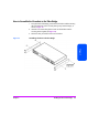
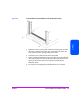
PDU Installation in the 10/180 Tape Library
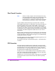
1. The PDU should be mounted in the bottom back of the rack. The outlets on
the PDU should face the back of the tape library. The power inlet should
be positioned on the right-hand side as you look at the back of the library.
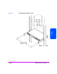
2. Attach the PDU to the holes in the left and right rails with the Torx screws
and hex nuts (see Figure 21 on page 60).
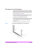
3. Tighten the screws to force the star washers to pierce the paint and make
solid contact with the metal column. This connects the rack chassis with
earth ground to protect against possible electric shock.
4. Connect the power cables from the devices to the PDU.
5. When connecting the PDU to the main power cable, secure the cable with
the clamp. Plug the main cable into the wall outlet. Verify that the current
capacity of the wall outlet to be used will not be exceeded by the
additional devices.
6. Do not power-on the bridge(s) until the SCSI devices are connected.
Figure 21 Power Distribution Unit Installation in the 10/180 Tape Library