
HP Surestore Bridge FC 2/1 LV and FC 4/1 HV Installation and Operations Guide


Chapter 3 Installing Cables 69
Chapter 3
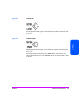
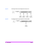
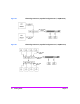
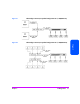
Fibre Bridge Connection, Expanded Configuration Example
(Tape Libraries Only)
Note This configuration is not supported for MO jukeboxes.
Caution Failure to turn off all power could result in damage to attached
devices.
1. Properly shut down all peripheral SCSI devices that will be connected to
the bridge.
2. Connect a SCSI cable from each bus (0 and 1 on the FC 2/1 LV, or 0
through 3 on the FC 4/1 HV) on the bridge to a tape drive in the library.
You may connect the library’s robotics controller to a spare bus on the
bridge or daisy chain it with a tape drive as long as the library robotics
controller and the tape drive are of the same SCSI bus type (HVD to HVD,
LVD to LVD).
3. Use the LVD converter (HP A6324A) to connect the library’s robotics
controller to a LVD SCSI bus.
4. You may daisy chain additional tape drives together, but this may result in
performance loss. Multiple bridges may be used within a single tape
library.
5. Connect the fibre cable from the bridge to the switch.
6. Connect a fibre cable from the switch to each host system.
7. Connect the power cord from the bridge to a power strip in the library.
8. Confirm that all cable ends are connected securely and that the end of
each bus is properly terminated. The bridge, in its default configuration,
provides internal termination at the end of each SCSI bus.
9. See Powering on the System on page 76.