
HP Surestore Bridge FC 2/1 LV and FC 4/1 HV Installation and Operations Guide


Chapter 4 Power-Up Messages for the FC 2/1 LV 81
Chapter 4
Power-Up Messages for the FC 2/1 LV
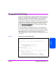
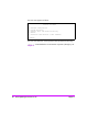
When you press the bridge’s power switch to the on position (marked with a
‘1’ symbol), a series of messages similar to the following appear on the
terminal or terminal emulation program:
Note The illustration in this chapter uses Xs to represent numeric values
for certain data fields, such as the product release version and
the revision of firmware.
Note If you do not see messages on your screen, re-check your
computer’s serial port settings and press
[Enter] five or six times.
In particular, make sure the baud rate is set to one of the values
listed in Setting Up Serial Port Communications on page 80.
Firmware X.X\XXXXXX
CPU Program RAM
PCI Protocol RAM
SCSI Script RAM (1)
SCSI Script RAM (2)
Ethernet POST Test
SCSI Post Test (1)
SCSI Post Test (2)
Fibre Channel Post
: XXXXXXXX
: XXXXXXXX
: XXXXXXXX
: XXXXXXXX
: PASSED
: PASSED
: PASSED
Target Name: generic
User: target
Attaching network interface lnPci0...done.
Attached TCP/IP interface to lnPci unit 0
Attaching network interface lo0...done.
NFS client support not included.
Initializing sioc...
Initializing SCSI port 0
SCRIPTS start @ 0x88004000
Initializing SCSI port 1
SCRIPTS start @ 0x88008000
(LVD)
(4144)
(LVD)
(4144)