installation instructions hp StorageWorks universal port module kit Product Version: FW V05.01.00-24/HAFM SW V07.01.00-09 Third Edition (June 2003) Part Number: AA–RSS2C–TE/958–000281–001 These installation instructions provide procedures for setting up, configuring, and managing a UPM kit in a StorageWorks Director 2/64 or a Director 2/140.
© Copyright 2001-2003 Hewlett-Packard Development Company, L.P. Hewlett-Packard Company makes no warranty of any kind with regard to this material, including, but not limited to, the implied warranties of merchantability and fitness for a particular purpose. Hewlett-Packard shall not be liable for errors contained herein or for incidental or consequential damages in connection with the furnishing, performance, or use of this material.
contents Contents About this Guide. . . . . . . . . . . . . . . . . . . . . . . . . . . . . . . . . . . . . . . . . . . . . . . . . . . .5 Overview. . . . . . . . . . . . . . . . . . . . . . . . . . . . . . . . . . . . . . . . . . . . . . . . . . . . . . . . . . . . . . . . . . 6 Intended Audience . . . . . . . . . . . . . . . . . . . . . . . . . . . . . . . . . . . . . . . . . . . . . . . . . . . . . . . 6 Related Documentation . . . . . . . . . . . . . . . . . . . . . . . . . . . . . . . . . . . . . . .
Contents 4 Universal Port Module Kit Installation Instructions
about this guide About this Guide These installation instructions provides information to help you: ■ Install the UPM kit. ■ Test the UPM kit for proper operation. ■ Contact technical support for additional assistance.
About this Guide Overview This section covers the following topics: ■ Intended Audience ■ Related Documentation Intended Audience This book is intended for use by owners of the HP StorageWorks Director 2/64 or the Director 2/140. Related Documentation For a list of corresponding documentation included with this product, see the Related Documents section of the HP StorageWorks Director Release Notes.
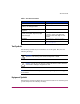
About this Guide Table 1: Document Conventions Element Convention Cross-reference links Blue text: Figure 1 Key and field names, menu items, buttons, and dialog box titles Bold File names, application names, and text emphasis Italics User input, command and directory names, and system responses (output and messages) Monospace font COMMAND NAMES are uppercase monospace font unless they are case sensitive Variables Website addresses Blue, underlined sans serif font text:
About this Guide Any enclosed surface or area of the equipment marked with these symbols indicates the presence of electrical shock hazards. Enclosed area contains no operator serviceable parts. WARNING: To reduce the risk of personal injury from electrical shock hazards, do not open this enclosure. Any RJ-45 receptacle marked with these symbols indicates a network interface connection.
About this Guide Any product or assembly marked with these symbols indicates that the component exceeds the recommended weight for one individual to handle safely. WARNING: To reduce the risk of personal injury or damage to the equipment, observe local occupational health and safety requirements and guidelines for manually handling material.
About this Guide Rack Stability Rack stability protects personnel and equipment. WARNING: To reduce the risk of personal injury or damage to the equipment, be sure that: ■ The leveling jacks are extended to the floor. ■ The full weight of the rack rests on the leveling jacks. ■ In single rack installations, the stabilizing feet are attached to the rack. ■ In multiple rack installations, the racks are coupled. ■ Only one rack component is extended at any time.
About this Guide Getting Help If you still have a question after reading this guide, contact an HP authorized service provider or access our website: http://www.hp.com. HP Technical Support Telephone numbers for worldwide technical support are listed on the following HP website: http://www.hp.com/support/. From this website, select the country of origin. Note: For continuous quality improvement, calls may be recorded or monitored.
About this Guide 12 Universal Port Module Kit Installation Instructions
Installation Instructions 1 1 This chapter describes the procedures used for installing a Universal Port Module (UPM) kit into a Director 2/64 or a Director 2/140.
Installation Instructions Supported Kits HP sells the StorageWorks Director 2/64 with a base configuration of 32 Fibre Channel ports and the StorageWorks Director 2/140 with a base configuration of 64 Fibre Channel ports. HP also sells optional kits to increase the number of ports to a maximum of 64 for the Director 2/64 and a maximum of 140 for the Director 2/140.
Installation Instructions Installing the UPM This section describes procedures to install one UPM card, even though you can install more than one UPM card at the same time. If you are installing more than one UPM card, ensure that the procedure steps are applied to all UPM cards being installed. In addition, this section provides procedural notes and ESD information. Procedural Notes The following procedural notes are referenced as applicable.
Installation Instructions Note: Figure 1 shows a cable management assembly for the Director 2/64 that is only used with the 9000, 10000, and 11000 Series cabinets. Note: For the Director 2/64, rotate the cable management assembly, if used, to reach the grounding point. The assembly locks into the raised position. Any cables attached to the Director 2/64 are then held up, allowing access to the lower front of the chassis. If no cables are attached to the director, the assembly may be removed.
Installation Instructions Figure 2: Director 2/140 ESD grounding points The ESD grounding point for the rear of the Director 2/140 chassis is located next to the maintenance port, as shown in Figure 2. The ESD grounding point for the rear of the Director 2/64 chassis is located at the bottom center, directly below the maintenance port, as shown in Figure 3.
Installation Instructions Touch the chassis once before performing any maintenance action, and once each minute while installing UPMs. 1 1 SHR 2300 ESD Grounding Point Figure 3: ESD grounding point (rear) Removing the UPM Filler Blank Use the following procedure to remove a UPM filler blank. Filler blanks cover and protect unused UPM card slots in the director chassis. A list of required tools is provided.
Installation Instructions The filler blank is secured to the director chassis with two captive Allen screws. Both screws are spring-loaded to lock the filler blank in place. 3. Insert the torque tool into each locking Allen screw, as shown in Figure 4 for the Director 2/64 and Figure 5 for the Director 2/140. Turn each screw counter-clockwise until the spring releases and the tool turns freely.
Installation Instructions Figure 5: Director 2/140 UPM filler blank removal 4. Pull the filler blank out and remove it from the director chassis. Installing the UPM Card Use the following procedures to install a UPM card. A list of required tools is provided. Required Tools The following tools are required to perform these procedures. 20 ■ ESD grounding cable and wrist strap. ■ Torque tool and hex adapter (provided with the director). ■ Fiber optic protective plugs (provided with the director).
Installation Instructions Installation 1. Follow ESD procedures by attaching a wrist strap to the director chassis. Caution: To avoid causing machine errors or damage while working on the director, follow ESD procedures by connecting a grounding cable to the director chassis and wearing an ESD wrist strap. Caution: Ensure that protective plugs are inserted into the UPM card optical transceiver receptacles.
Installation Instructions Figure 7: Director 2/140 UPM card installation 2. Remove the UPM card from its protective anti-static bag. 3. Hold the card by its stiffener and insert it in the chassis card track, as shown in Figure 6 for the Director 2/64 and Figure 7 for the Director 2/140. The yellow locking Allen screw should be at the bottom for the Director 2/64, and it should align with the yellow “lock” symbols on the frame for the Director 2/140.
Installation Instructions Caution: The torque tool supplied with the director is designed to tighten logic cards and is set to release at a torque value of six inch-pounds. Do not use an Allen wrench or torque tool designed for use with another HP or Compaq product. Use of the wrong tool may overtighten and damage logic cards. a. Insert the torque tool into the cam Allen screw (uncolored). Turn the torque tool clockwise until you feel it release and hear a clicking sound.
Installation Instructions 11. At the Hardware View, double-click the graphic representing the replacement card to open the Port Card View. At the Port Card View: a. Ensure no alert symbols display that indicate a failure (yellow triangle or red diamond). b. Verify UPM card information (FRU name, position, and state) is correct. If a problem is indicated, go to MAP 0000: Start MAP of the HP StorageWorks Director 2/64 Service Manual or HP StorageWorks Director 2/140 Service Manual to isolate the problem. 12.
Installation Instructions — Port card type (UPM). — Chassis slot number (0 through 15 inclusive for the Director 2/64; 0 through 35 inclusive (excluding 32) for the Director 2/140). — The four consecutive port numbers on the selected card. Valid port numbers are in the range of 0 through 63 inclusive for the Director 2/64. Valid port numbers are in the range of 0 through 143 inclusive (excluding 128 through 131) for the Director 2/140. 5. Reset each port to be tested: a.
Installation Instructions Figure 8: Port Diagnostics dialog box 9. Select a port or UPM card for test, perform one of the following: — To select an individual port for test, type the port number in the Port Number field. — To select a UPM card for test, type the port number of any of the four ports an the card in the Port Number field, then choose All Ports On Card. 10. At the Diagnostics Test list box, choose External Loopback. 11. Click Next.
Installation Instructions — The message Port xx: TEST RUNNING displays, where xx is the port number. If a UPM card is tested, the message displays for all four ports. — A red progress bar (indicating percent completion) travels from left to right across the Completion Status field. As an individual port is tested, the amber LED flashes (beacons) and the green LED illuminates (indicating loopback traffic through the port). Note: Click Stop Test at any time to abort the loopback test. 15.
Installation Instructions 4. Move the cursor over the UPM card to be unblocked (but not over an individual port) and right-click the mouse to open a list of menu options. 5. Choose Unblock All Ports option. The Unblock All Ports dialog box displays, as shown in Figure 9. Figure 9: Unblock All Ports dialog box 6. Click Yes. The following occurs to indicate the UPM card is unblocked, and the attached devices are online: — Emulated green LEDs associated with all four ports illuminate at the Port Card View.