
fw 05.01.00 and sw 07.01.00 - Universal Port Module Kit - Installation Instructions

Installation Instructions
25Universal Port Module Kit Installation Instructions
— Port card type (UPM).
— Chassis slot number (0 through 15 inclusive for the Director 2/64; 0
through 35 inclusive (excluding 32) for the Director 2/140).
— The four consecutive port numbers on the selected card. Valid port
numbers are in the range of 0 through 63 inclusive for the Director 2/64.
Valid port numbers are in the range of 0 through 143 inclusive (excluding
128 through 131) for the Director 2/140.
5. Reset each port to be tested:
a. At the Hardware View, double-click the UPM card for which ports are to
be tested. The Port Card View displays.
b. At the Port Card View, right-click the tested port. A menu displays.
c. Choose Reset Port. A Reset Port n message box displays, where n
is the port number.
d. Click OK. The port resets.
e. Click Back To Full View to return to the Hardware View.
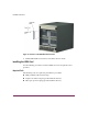
6. Disconnect the fiber optic jumper cable from the port to be tested. If a UPM
card will be tested, disconnect all four fiber optic jumper cables.
Note: If name server zoning is implemented by port number, ensure fiber optic cables
that are disconnected to perform the loopback test are reconnected properly. A cable
configuration change disrupts zone operation and may incorrectly include or exclude
a device from a zone.
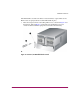
7. If the port to be tested is shortwave laser, insert a multimode loopback plug
into the port receptacle. If the port to be tested is longwave laser, insert a
single mode loopback plug into the port receptacle. If an entire UPM card will
be tested, insert an appropriate loopback plug in all four port receptacles.
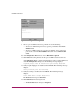
8. Choose Port Diagnostics from the Maintenance menu. The Port
Diagnostics dialog box displays, as shown in Figure 8.