
HP CPCI Interface Kit With LVD SCSI Adapter Card Installation Instructions

17
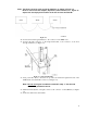
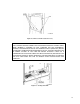
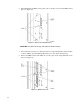
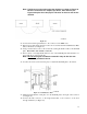
Note: The library must be at the end of the SCSI bus as shown in Figure 26.
Devices can be host bus adapter, tape drives, other libraries, etc.
Figure 26 depicts the actual physical location on the bus and not the
SCSI ID.
Figure 26.
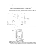
24. Connect the feed-through terminator to the connector on the MPW card.
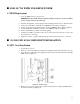
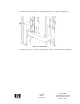
25. Release upper cable clamp and remove the four screws that attach the SCSI Interface Plate
(I/F) to the chassis (see Figure 27).
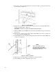
26. Using a 3/16 hex driver, remove the screwlocks securing the SCSI Y cable to the SCSI I/F
plate. Discard the cable and the screwlocks.
27. Insert connector of straight SCSI cable into slots on the SCSI I/F plate and attach the con-
nector with the provided screwlocks.
Note: Do not use
original screwlocks removed in Step 26. Use the new
screwlocks provided in the kit.
28. Use the four screws (removed in Step 25) to reattach the SCSI I/F plate to the chassis.
Figure 27. SCSI Interface Plate
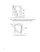
29. Obtain the LVD SCSI icon and place it on the SCSI I/F plate to the right of the connector
(see Figure 28).
30. Connect the male connector, on the single SCSI cable, to the connector on the feed-
through terminator (see Figure 28).