
ISS Technology Update, Volume 7 Number 3 - Newsletter


ISS Technology Update Volume 7, Number 3
6
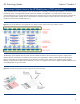
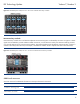
Figure 2-3. HP BladeSystem c7000, front view. The arrows indicate device bay crosslinks.
Interconnect bay crosslinks
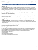
Interconnect bay crosslinks are wired between adjacent interconnect bay pairs as indicated by the arrows in Figure 2-4. These
signals can be enabled to provide module-to-module connections, such as Ethernet crosslink ports between matching switches,
or to provide stacking links for Virtual Connect modules. The Onboard Administrator disables the interconnect bay crosslinks in
instances where they cannot be used, for example, if two different modules reside in adjacent horizontal interconnect bays.
Figure 2-4. HP BladeSystem c7000, rear view. The arrows indicate interconnect bay crosslinks.
Additional resources
Visit these resources for additional information on the topics discussed in this article:
Resource URL
“HP BladeSystem C7000 Enclosure,
3rd Edition” technology brief
http://h20000.www2.hp.com/bc/docs/support/SupportManual/c00816246/c00816246.pdf
HP BladeSystem Onboard
Administrator User Guide
http://h20000.www2.hp.com/bc/docs/support/SupportManual/c00705292/c00705292.pdf