HP R3000v ERM User Guide
© Copyright 2008 Hewlett-Packard Development Company, L.P. The information contained herein is subject to change without notice. The only warranties for HP products and services are set forth in the express warranty statements accompanying such products and services. Nothing herein should be construed as constituting an additional warranty. HP shall not be liable for technical or editorial errors or omissions contained herein.
Special Symbols The following are examples of symbols used on the UPS or accessories to alert you to important information: RISK OF ELECTRIC SHOCK - Observe the warning associated with the risk of electric shock symbol. CAUTION: REFER TO OPERATOR’S MANUAL - Refer to your operator’s manual for additional information, such as important operating and maintenance instructions. This symbol indicates that you should not discard the UPS or the UPS batteries in the trash.
/ (SLA) / O: SJ/T11363-2006 X: SJ/T11363-2006 2003 1 X 27 RoHS 2002/95/EC (UPS) (PDU) (ERM) HP / (SLA) UPS
Table of Contents 1 2 3 Introduction . . . . . . . . . . . . . . . . . . . . . . . . . . . . . . . . . . . . . . . . . . . . . . . . . . . . . . . . 1 Safety Warnings . . . . . . . . . . . . . . . . . . . . . . . . . . . . . . . . . . . . . . . . . . . . . . . . . . . . . . . . . . . . . . . . . . 1 Installation . . . . . . . . . . . . . . . . . . . . . . . . . . . . . . . . . . . . . . . . . . . . . . . . . . . . . . . . . 3 Inspecting the Equipment . . . . . . . . . . . . . . . . . . . . . . . .
TABLE OF CONTENTS ii HP R3000v ERM User Guide S 164201732 Rev 1
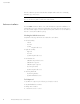
Chapter 1 Introduction The Extended Runtime Module (ERM) can be added to the HP R3000v Uninterruptible Power System (UPS) to extend the available battery time (see Table 1). Up to four ERMs can be installed with the UPS.
INTRODUCTION 2 HP R3000v ERM User Guide S 164201732 Rev 1
Chapter 2 Installation NOTE: If you are installing the UPS and the Extended Runtime Module (ERM) together, follow the installation instructions in the UPS user guide. NOTE: ERMs can be installed easily without turning the UPS off or disconnecting the load. If you prefer to remove input power to install an ERM, refer to “UPS Shutdown” in the UPS user guide.
INSTALLATION Place the cabinet in a protected area that has adequate airflow and is free of humidity, flammable gas, and corrosion. NOTE: Discard the ERM user guide if you are installing the ERM with a new UPS at the same time. Use the UPS user guide to install both the UPS and ERM. Rackmount Installation The HP R3000v rackmount cabinet comes with all hardware required for installation in a standard EIA or JIS seismic rackmount configuration with square and round mounting holes.
INSTALLATION Rackmount Setup CAUTION S The cabinet is heavy (see page 17). A minimum of two people are required to remove the cabinet from its carton. S Install the ERM(s) directly below the UPS so that all wiring between the cabinets is installed behind the front bezels and is inaccessible to users. NOTE: Mounting rails are required for each individual cabinet. To install the rail kit: 1. Attach the left and right rails to the rear rails as shown in Figure 1. Do not tighten the screws.
INSTALLATION 2. Select the proper holes in the rack for positioning the ERM in the rack (see Figure 2). The rails occupy four positions on the front and rear of the rack. 3. Secure one rail assembly to the front of the rack with one M6×16 pan-head screw and one M6 cage nut. 4. Using two M6 cage nuts and two M6×16 pan-head screws, attach the rail assembly to the rear of the rack. Position 4 Position 1 M6 Cage Nuts (6 places) Tighten adjustment screws after rail attachment (3 places each rail).
INSTALLATION 11. Slide the cabinet(s) into the rack. 12. Secure the front of the ERM to the rack using two M6×16 pan-head screws and two M6 cage nuts on each side (see Figure 4). Install the bottom screw on each side through the bottom hole of the mounting bracket and the bottom hole of the rail. Repeat for any additional ERMs. M6 Cage Nuts (4 places) M6×16 Pan-Head Screws (4 places) Figure 4 Securing the Front of the Cabinet 13. Optional.
INSTALLATION Rackmount Wiring Installation To install the ERM: 1. Remove the UPS right front bezel (behind the control panel). See Figure 6. To remove the bezel, loosen the two captive screws on the right side of the bezel. Grasp the top and bottom of the bezel and slide the bezel to the right. NOTE: A ribbon cable connects the control panel to the UPS. Do not pull on the cable or disconnect it. NOTE: Leave ribbon cable connected. Figure 6 Removing the UPS Right Front Bezel 2.
INSTALLATION 3. Remove the front bezel of each ERM. See Figure 8. To remove the bezel, loosen the two captive screws on the right side of the bezel. Grasp the sides of the bezel and slide the bezel to the left and then away from the cabinet. Top ERM Cable Knockout ERM Bezel Hook Bottom ERM Cable Knockout (underneath bezel) Figure 8 Removing the ERM Front Bezel 4. For the bottom (or only) ERM, remove the ERM cable knockout on the top of the ERM front bezel.
INSTALLATION NOTE: A small amount of arcing may occur when connecting an ERM to the UPS. This is normal and will not harm personnel. Insert the ERM cable into the UPS battery connector quickly and firmly. 6. Plug the ERM cable(s) into the battery connector(s) as shown in Figure 9. Up to four ERMs may be connected to the UPS. Connect red to red, black to black, and green to green. Press the two parts tightly together to ensure a proper connection.
Chapter 3 Maintenance This section explains how to: S Care for the ERM S Replace the ERM S Recycle used batteries or UPS ERM Care For the best preventive maintenance, keep the area around the ERM clean and dust-free. If the atmosphere is very dusty, clean the outside of the system with a vacuum cleaner. For full battery life, keep the ERM at an ambient temperature of 25°C (77°F). Replacing ERMs NOTE: DO NOT DISCONNECT the batteries while the UPS is in Battery mode.
MAINTENANCE CAUTION The ERM is heavy (see page 17). A minimum of two people are required to lift the cabinet into the rack. To replace the ERMs: 1. Remove the UPS right front bezel (see Figure 10). To remove the bezel, loosen the two captive screws on the right side of the bezel. Grasp the top and bottom of the bezel and slide the bezel to the right. NOTE: A ribbon cable connects the control panel to the UPS. Do not pull on the cable or disconnect it. NOTE: Leave ribbon cable connected.
MAINTENANCE 2. Remove the front bezel of each ERM. See Figure 11. To remove the bezel, loosen the two captive screws on the right side of the bezel. Grasp the sides of the bezel. Slide the bezel to the left and then away from the cabinet. Top ERM Cable Knockout ERM Bezel Hook Bottom ERM Cable Knockout (underneath bezel) Figure 11 Removing the ERM Front Bezel 3. Unplug the ERM cable from the UPS. If additional ERMs are installed, unplug the ERM cable from the battery connector on each ERM. 4.
MAINTENANCE 9. Plug the ERM cable(s) into the battery connector(s) as shown in Figure 9 on page 10. Connect red to red, black to black, and green to green. Press the two parts tightly together to ensure a proper connection. To connect a second ERM, unclip the ERM connector on the first ERM and pull gently to extend the wiring to the ERM connector on the second ERM. Repeat for any additional ERMs. 10.
MAINTENANCE Recycling the Used Battery or UPS Contact your local recycling or hazardous waste center for information on proper disposal of the used battery or UPS. WARNING S Do not dispose of the battery or batteries in a fire. Batteries may explode. Proper disposal of batteries is required. Refer to your local codes for disposal requirements. S Do not open or mutilate the battery or batteries. Released electrolyte is harmful to the skin and eyes. It may be toxic.
MAINTENANCE 16 HP R3000v ERM User Guide S 164201732 Rev 1
Chapter 4 Specifications This section provides the following specifications: S Weight and dimensions S Battery specification Table 2 Weight and Dimensions Model HP R3000v ERM Dimensions (H×W×D) Weight 86.7 ×438.0×601.6 mm (3.41”×17.24”×23.69”) 38.1 kg (84.
SPECIFICATIONS 18 HP R3000v ERM User Guide S 164201732 Rev 1
Chapter 5 Service and Support To obtain replacement ERMs or to receive factory authorized service, contact an HP approved service provider with the following information: China: India: 400 8899 102 1 800 102 3330 UPS Part Number: UPS Serial Number: AF443A 3C8zzzzzzz One Year Limited Warranty MODELS: HP T1000v UPS, HP R3000v UPS, and HP R3000v ERM WARRANTOR: The warrantor for the limited warranties set forth herein is Hewlett-Packard Company (Company).
SERVICE AND SUPPORT 20 HP R3000v ERM User Guide S 164201732 Rev 1
HP R3000v ERM 用户指南
© 版权所有 2008 Hewlett-Packard Development Company, L.P.
特殊符号 以下为 UPS 或配件上使用的一些符号示例,用于警示重要信息: 电击危险 - 注意与电击危险符号相关的警告信息。 小心:请参见操作手册 - 参见操作手册获取详细信息,如重要操作和维护说明。 此符号表示您不能将 UPS 或 UPS 电池丢弃到垃圾箱中。 本产品包含密封铅酸电池,必须妥善处理。 有关 详细信息,请联系当地回收机构或危险废物处理中心。 此符号表示您不能将废弃电气或电子设备 (WEEE) 丢弃到垃圾箱中。 有关妥善处理信息,请联系当地回收机 构或危险废物处理中心。 National Electrical Code 和 NEC 是 National Fire Protection Association, Inc.
/ (SLA) / O: SJ/T11363-2006 X: SJ/T11363-2006 2003 1 27 X RoHS 2002/95/EC (UPS) (PDU) (ERM) (SLA) / HP UPS
目录 1 简介.............................................................. 1 安全警告..........................................................................1 2 安装.............................................................. 3 检查设备..........................................................................3 机箱拆包..........................................................................3 机架安装..........................................................................4 检查滑轨配件.........................................
目录 ii HP R3000v ERM 用户指南 • 164201732 修订版 1
第 1 章 简介 HP R3000v 不断电系统 (UPS) 中可添加扩展运行时模块 (ERM),以延长电池的工 作时间(参见表 1)。UPS 最多可安装 4 个 ERM。 表 1 满负荷情况下的电池工作时间(分钟) 型号 HP R3000v UPS 内部电池 + 1 ERM + 2 ERM + 3 ERM + 4 ERM 3 18 34 53 69 安全警告 重要安全说明 请保留这些说明 本手册包含重要说明,您在安装和维护 UPS 与电池应该严格遵守。请在操作设备之 前阅读所有说明,并将本手册妥善保管以便将来参考。 警告 S 本 UPS 包含自供电电源(电池)。即使 UPS 未与交流电源相连,输出端也可能存 在电压。 小心 S 在高短路电流下电池可能存在电击或自然危险。注意采取预防措施。维修只能由掌 握电池相关知识和所需预防措施的合格维修人员进行。未经授权的人员不能接触电 池。 S 电池必须妥善处理。 请参考当地有关如何处置的要求。 S 切勿将电池丢入火中。 将电池投入火中可能会引起爆炸。 S 如果需要运输 UPS,请在运输前断开 UPS 的内部电池(参见 UPS 用户指
简介 HP R3000v ERM 用户指南 • 164201732 修订版 1
第 2 章 安装 注意:如果同时安装 UPS 和扩展运行时模块 (ERM),请安装 UPS 用户指南中的安装 说明进行操作。 注意:不必关闭 UPS 或断开负载即可非常简便地安装 ERM。如果要断开输入电源后安 装 ERM,请参见 UPS 用户指南中的“UPS 关机”。 本部分介绍: S S S S 设备检查 机箱拆包 检查配件包 ERM 安装 检查设备 如果任何设备在运输过程中损坏,请保留运输纸箱和包装材料原样交给运输商或购 买地点,并填写一份运输损坏声明。如果您在收货后发现损坏,请填写一份隐蔽损 坏声明。 要填写运输损坏或隐蔽损坏声明:1)在接收设备的 15 天内将声明交给运输商; 2)在 15 天内将损坏声明副本寄送给服务代表。 注意:检查运输箱标签上的电池充电日期。如果已经过期并且电池从未充电,请勿使 用 UPS。请联系服务代表。 机箱拆包 小心 S 在低温环境下拆开机箱包装可能导致机箱及其内部发生冷缩现象。请在机箱内外完 全干燥后再安装(以防电击危险)。 S 机箱非常重(参见第 17 页)。请在拆开包装和搬动机箱时特别小心。 请小心搬动和打开包装箱。直到准备安装时才拆开元件包装。
安装 将机箱放置在通风良好、干燥且不存在易燃性气体和腐蚀的安全环境中。 注意:如果同时安装 ERM 和新 UPS,请忽略 ERM 用户指南。使用 UPS 用户指南安 装 UPS 和 ERM。 机架安装 HP R3000v 机架机箱配备所有安装所需的硬件和标准 EIA 或 JIS 级防震机架配 置,带有方形和圆形安装孔。滑轨组件可调整安装到 48 CM(19 英寸)的机架 上,前端离后部滑轨距离 61 到 76 CM(24 到 30 英寸)深。 检查滑轨配件 确定每个机箱随附下列滑轨物品: S 左滑轨组件: - 左滑轨 - 后部滑轨 - (3) M4x8 截锥头螺钉 S 右滑轨组件: - 右滑轨 - 后部滑轨 - (3) M4x8 截锥头螺钉 S 滑轨硬件套件: - (10) M6x16 截锥头螺钉 - (10) M6 六角卡式螺母 - (10) M6 方形卡式螺母 - (2) 后部阻挡支架 - (6) M3x8 截锥头螺钉 S 固定支架套件: - (2) 固定支架 - (8) M4x6 平头螺钉 所需工具 组装元件时需要用到下列工具: S 中号一字螺丝刀 S Phillips® 2 号螺丝
安装 机架安装 小心 S 机箱非常重(参见第 17 页)。至少需要两个人才能将机箱从包装中取出。 S 请将 ERM 安装在 UPS 的正下方,以便机箱间所有配线都安装在前盖的后面,避免 用户接触。 注意: 根据需要为每个机箱安装滑轨。 安装滑轨配件: 1.
安装 2. 选择机架中适当的孔,将 ERM 固定到机架中(参见图 2)。滑轨占据机架前部 和后部的四个位置。 3. 使用一个 M6x16 的前部。 截锥头螺钉和一个 M6 卡式螺母将一个滑轨组件固定到机架 4. 使用两个 M6 卡式螺母和两个 M6x16 后部。 截锥头螺钉,将滑轨组件固定到机架的 位置 44 Position 位置 11 Position M6 M6卡式螺母 Cage Nuts (6 places) (6 处位置) Tighten 连接滑轨后拧紧调节螺钉 adjustment (每个滑轨 3 处位置)。 M4x8 截锥头螺钉 16 Pan-Head M6 (6 处位置) Screws (6 places) screws after rail attachment (3 places each rail). 机架前部 Front of Rack 图 2 固定滑轨 5. 对其它滑轨组件重复步骤 3 和 4。 6. 拧紧每个滑轨组件中部的三个调节螺钉。 7. 如果安装多个 ERM,请对每个滑轨套件重复步骤 1 至步骤 6。 8.
安装 11. 将机箱滑入机架中。 12. 每侧使用两个 M6x16 截锥头螺钉和两个 M6 卡式螺母,将 ERM 的前部固定 到机架上(参见图 4)。通过固定支架和滑轨的底部孔,安装每侧的底部螺 钉。 对所有额外 ERM 重复上述步骤。 M6 Cage Nuts (4 places)处位置) M6 卡式螺母(4 M6x16 截锥头螺钉 M6 16 Pan-Head Screws places) (4 (4 处位置) 图 4 固定机箱前部 13.
安装 机架配线安装 安装 ERM: 1. 取下 UPS 右前盖(控制面板的后面)。参见图 6。 要取下盖板,请松开前盖右侧的两个系留螺钉。抓住盖板的顶部和底部,将其 滑动到右侧。 注意:控制面板通过带状线缆与 UPS 相连。请勿拖拽线缆或断开其连接。 注意:保持带状线缆相连。 Leave NOTE: ribbon cable connected. 图 6 取下 UPS 右前盖 2.
安装 3. 取下每个 ERM 的前盖。参见图 8。 要取下盖板,请松开前盖右侧的两个系留螺钉。抓住前盖的侧面,将其滑动到 左侧,然后滑出机箱。 顶部 ERMCable 线缆接线口 Top ERM Knockout ERM 盖钩 ERM Bezel Hook Bottom ERM Cable Knockout 底部 ERM 线缆接线口(盖板下方) (underneath bezel) 图 8 取下 ERM 前盖 4. 对于底部(或仅限)ERM,在 ERM 前盖的顶部,取下用于 ERM 线缆连接的阻 塞物。有关顶部 ERM 线缆连接阻塞物的位置,请参见图 8。 5.
安装 注意:连接 ERM 和 UPS 时可能会出现少量火花。这是正常现象,不会对人员产生伤 害。将 ERM 线缆迅速稳固地插入 UPS 电池接线器中。 6. 将 ERM 线缆插入电池接线器中,如图 9 所示。UPS 最多可连接 4 个 ERM。 将红对红、黑对黑、绿对绿相连。将两个部件紧紧按压在一起,以确保牢固连 接。 要连接第二个 ERM,请解开第一个 ERM 上的 ERM 接线器,并轻轻拉出配线连 接到第二个 ERM 上的 ERM 接线器。对所有额外 ERM 重复上述步骤。 7. 确保 ERM 连接稳固,而且每根线缆具有足够的弯曲半径和应变释放。 图 9 典型 ERM 安装 8. 更换 ERM 前盖。 要更换前盖,请确保 ERM 线缆已通过 ERM 前盖阻塞物。将前盖从左向右滑 动,直到与 ERM 机箱左侧附近的盖钩相连。拧紧前盖右侧的两个系留螺钉。 请参见第 9 页的图 8。 对每个额外 ERM 重复上述步骤。 9. 确保 UPS 和 ERM 的所有配线连接都安装在前盖的后面,并且用户无法接触。 10.
第 3 章 维护 本部分介绍如何: S ERM 保养 S 更换 ERM S 回收利用废弃电池或 UPS ERM 保养 为了提供最好的预防性维护,请保持 ERM 周围的环境清洁无尘。如果空气灰尘较 大,请使用真空吸尘器清洁 UPS 外部。 为了保持电池最大使用寿命,请保持 ERM 周围环境温度为 25°C (77°F)。 更换 ERM 注意:UPS 处于电池模式时切勿断开电池连接。 不必关闭 UPS 或断开负载即可非常简便地更换 ERM。如果要断开输入电源后进行 更换,请参见 UPS 用户指南中的“UPS 关机”。 更换 ERM 前请考虑所有警告、小心、注意等信息。 警告 S S S S 电池必须妥善处理。请参考当地有关如何处置的要求。 切勿将电池丢入火中。将电池投入火中可能会引起爆炸。 请勿打开或损坏电池。溢出的电解液对皮肤和眼睛有害,毒性可能非常大。 电击危险。请勿尝试更改任何电池连线或接线器。尝试更改连线可能导致人身伤 害。 S 断开充电电源后,再连接或断开电池接线端。 HP R3000v ERM 用户指南 • 164201732 修订版 1 11
维护 小心 ERM 非常重(参见第 17 页)。至少需要两个人才能将机箱抬起装入机架中。 要更换 ERM: 1. 取下 UPS 右前盖(参见图 10)。 要取下盖板,请松开前盖右侧的两个系留螺钉。抓住盖板的顶部和底部,将其 滑动到右侧。 注意: 控制面板通过带状线缆与 UPS 相连。请勿拖拽线缆或断开其连接。 注意: 保持带状线缆相连。 Leave NOTE: ribbon cable connected.
维护 2. 取下每个 ERM 的前盖。参见图 11。 要取下盖板,请松开前盖右侧的两个系留螺钉。抓住盖板的侧面。将盖板滑到 左侧,从机箱中拉出。 顶部 ERM 线缆接线口 Top ERM Cable Knockout ERM 盖钩 ERM Bezel Hook Bottom ERM线缆接线口(盖板下方) Cable Knockout 底部 ERM (underneath bezel) 图 11 取下 ERM 前盖 3. 断开 ERM 线缆与 UPS 的连接 如果安装了额外的 ERM,请确保每个 ERM 的线缆都与电池接线器断开连接。 4. 如果尚未安装,请在新 ERM 上安装提供的固定支架。 5. 更换 ERM。请参见第 15 页的“废弃电池或 UPS 循环利用”了解有关正确处 理方式。 6. 取下每个新 ERM 的前盖。参见图 11。 要取下盖板,请松开前盖右侧的两个系留螺钉。抓住盖板的侧面。将盖板滑到 左侧,从机箱中拉出。 7. 对于底部(或仅限)ERM,在前盖的顶部,取下用于 ERM 线缆连接的阻塞物。 有关顶部 ERM 线缆连接阻塞物的位置,请参见图 11。 8.
维护 9. 将 ERM 线缆插入电池接线器中,如第 10 页图 9 所示。 将红对红、黑对黑、绿对绿相连。将两个部件紧紧按压在一起,以确保牢固连 接。 要连接第二个 ERM,请解开第一个 ERM 上的 ERM 接线器,并轻轻拉出配线连 接到第二个 ERM 上的 ERM 接线器。对所有额外 ERM 重复上述步骤。 10. 确保 ERM 连接稳固,而且每根线缆具有足够的弯曲半径和应变释放。 11. 更换 ERM 前盖。 要更换前盖,请确保 ERM 线缆已通过 ERM 前盖接线口,然后将前盖从左向 右滑动,直到与 ERM 机箱左侧附近的盖钩相连。拧紧前盖右侧的两个系留螺 钉。请参见第 13 页的图 11。 对每个额外 ERM 重复上述步骤。 12. 确保 UPS 和 ERM 的所有配线连接都安装在前盖的后面,并且用户无法接触。 13. 更换 UPS 右前盖。 测试新电池 注意:UPS 对其内部电池和所有相连 ERM 执行电池测试。 要测试新电池: 1. 将 UPS 插入电源插座,为电池充电 48 小时。 2. 按压 UPS 前面板上的 (输出开启)按钮至少 1 秒钟。 3.
维护 回收利用废弃电池或 UPS 有关正确处理废弃电池或 UPS 的信息,请联系当地回收中心或危险废弃物处理中 心。 警告 S 请勿将电池丢入火中。否则电池可能会爆炸。电池必须妥善处理。请参考当地有关 如何处置的要求。 S 请勿打开或损坏电池。溢出的电解液对皮肤和眼睛有害, 其可能有毒性。 小心 请勿将 UPS 或 UPS 电池丢弃到垃圾箱中。本产品包含密封铅酸电池,必须妥善处 理。有关详细信息,请联系当地回收机构或危险废物处理中心。 小心 请勿将废弃电气或电子设备 (WEEE) 丢弃到垃圾箱中。有关妥善处理信息,请联系当 地回收机构或危险废物处理中心。 HP R3000v ERM 用户指南 • 164201732 修订版 1 15
维护 16 HP R3000v ERM 用户指南 • 164201732 修订版 1
第 4 章 规格 本章提供以下规格: S 重量和尺寸 S 电池规格 表 2 重量和尺寸 型号 HP R3000v ERM 尺寸(高 宽 深) 重量 86.7 x 438.0 x 601.6 mm (3.41”x 17.24”x 23.69”) 38.1 kg (84.
规格 18 HP R3000v ERM 用户指南 • 164201732 修订版 1
第 5 章 服务与支持 要获取备用 ERM 或接受工厂授权维修,请使用以下信息联系 HP 认证的维修提供 商: 中国: 印度: 400 8899 102 1 800 102 3330 UPS 部件号: AF443AUPS 序列号: 3C8zzzzzzz 一年有限担保 型号: HP T1000v UPS、HP R3000v UPS 和 HP R3000v ERM 担保人: 此处有限担保的担保人是 Hewlett-Packard Company(公司)。 有限担保: 本有限担保(本“担保”)仅适用任何 HP T1000v UPS、HP R3000v UPS 和 HP R3000v ERM 产品(单独或多个,“产品”)的原始最终用户(“最终用户”)。 即使“产品”由“公司”初始出售给供应商然后再分销给“最终用户”,本“担 保”仍然适用。 有限担保期限: 本“担保”的期限为购买之日起的十二 (12) 个月。 本有限担保覆盖范围: 担保人担保“产品”和电池(单独或同时,“受担保物品”)不存在材料和工艺上 的缺陷。 如果“公司”认定“受担保物品”存在缺陷,且该缺陷在本“担保”覆 盖范围之内,“公司”的
服务与支持 20 HP R3000v ERM 用户指南 • 164201732 修订版 1