
HP R3000v ERM User Manual

INSTALLATION
HP R3000v ERM User Guide S 164201732 Rev 1
10
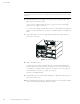
NOTE: A small amount of arcing may occur when connecting an ERM to the UPS. This is
normal and will not harm personnel. Insert the ERM cable into the UPS battery connector quickly
and firmly.
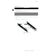
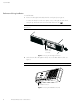
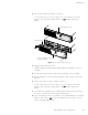
6. Plug the ERM cable(s) into the battery connector(s) as shown in Figure 9. Up to four
ERMs may be connected to the UPS.
Connect red to red, black to black, and green to green. Press the two parts tightly
together to ensure a proper connection.
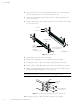
To connect a second ERM, unclip the ERM connector on the first ERM and pull gently to
extend the wiring to the ERM connector on the second ERM. Repeat for any additional
ERMs.
7. Verify that the ERM connections are tight and that adequate bend radius and strain
relief exist for each cable.
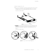
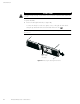
Figure 9 Typical ERM Installation
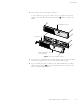
8. Replace the ERM front bezel.
To replace the bezel, verify that the ERM cables are routed through the ERM bezel
knockouts. Slide the bezel from the left to the right until it connects with the bezel hook
near the left side of the ERM cabinet. Tighten the two captive screws on the right side
of the front bezel. For reference, see Figure 8 on page 9.
Repeat for each additional ERM.
9. Verify that all wiring connecting the UPS and ERM(s) is installed behind the front bezels
and is inaccessible to users.
10. Ensure maximum battery runtime by configuring the UPS for the correct number of ERMs
(refer to the HP Value UPS Manager software for details).