
HP R3000v UPS User Manual

INSTALLATION
HP R3000v UPS User Guide S 164201731 Rev 1
8
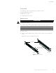
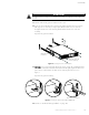
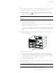
2. SelecttheproperholesintherackforpositioningtheUPSintherack(seeFigure4).
The rails occupy four positions on the front and rear of the rack.
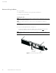
3. Secure one rail assembly to the front of the rack with one M6
×16 pan-head screw
and one M6 cage nut.
4. Using two M6 cage nuts and two M6
×16 pan-head screws, attach the rail assembly
to the rear of the rack.
M6×16 Pan-Head
Screws (6 places)
Front of Rack
M6 Cage Nuts
(6 places)
Tighten
adjustment
screws after rail
attachment
(3 places each rail).
Position 4
Position 1
Figure 4 Securing the Rails
5. Repeat Steps 3 and 4 for the other rail assembly.
6. Tighten the three adjustment screws on each rail assembly.
7. If installing optional cabinets, repeat Step 1 through Step 6 for each rail kit.
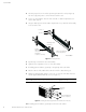
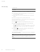
8. Place the UPS on a flat, stable surface with the front of the cabinet facing you.
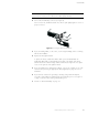
9. Align the mounting brackets with the screw holes on each side of the UPS and secure
with the supplied M4
×6 flat-head screws (see Figure 5).
NOTE: There are two sets of four m ounting holes on each side of the UPS: a forward position
and a middle position. Choose the position that meets your configuration needs.
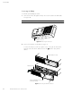
Mounting
Bracket
M4×6Flat-Head
Screws (4 places)
Figure 5 Installing the Mounting Brackets (Forward Position Shown)
10. If installing optional cabinets, repeat Steps 8 and 9 for each cabinet.