HP Value UPS Manager User’s Manual Part number 500276-001 September 2008 (First Edition)
© Copyright 2008 Hewlett-Packard Development Company, L.P. The information contained herein is subject to change without notice. The only warranties for HP products and services are set forth in the express warranty statements accompanying such products and services. Nothing herein should be construed as constituting an additional warranty. HP shall not be liable for technical or editorial errors or omissions contained herein.
Table of Contents CHAPTER 1 HP VALUE UPS MANAGER INTRODUCTION............................................................................ 2 1. HP VALUE UPS MANAGER OVERVIEW .................................................................................................................. 2 2. HP VALUE UPS MANAGER STRUCTURE ................................................................................................................ 2 3. HP VALUE UPS MANAGER SUPPORTED CONFIGURATION .........................
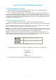
Chapter 1 HP Value UPS Manager Introduction 1. HP Value UPS Manager Overview HP Value UPS Manager is UPS monitoring software that supports either individual computer or computers connected to a network (including LAN & WAN). It is used to monitor the intelligent device and safeguard computer systems from unexpected crash when power fails. With HP Value UPS Manager, users can monitor and configure the device on any computer in the same LAN.
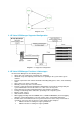
Diagram 1-2-2 3. HP Value UPS Manager Supported Configuration Diagram 1-3-1 Supported configuration 4. HP Value UPS Manager Functions & Advantages HP Value UPS Manager has the following features: 9 Agent starts runs continuously, protecting your equipment. 9 Uninstalls easily and completely. Never increases spending on the system and it is green software. 9 Provides a panoramic view of all the information including utility power, device, loads and battery status. 9 Auto searches any device on the LAN.
¾ With the function of sending messages via mobile phone sending SMS. Chapter 2 HP Value UPS Manager Installation, Start & Uninstall 1. System Minimum Requirements ¾ ¾ ¾ ¾ ¾ ¾ ¾ 128 MB physical memory (256MB is recommended). 160 MB hard disk space. More than 256 colors and 800 * 600 resolutions or above display is recommended. The user is required to have administrator rights. For Linux operating system, the user must log in the system with “root” account to carry out the installation.
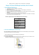
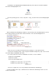
For Windows, enter \Windows\Disk1\InstData\VM directory. Run setup.exe to start the installation. Refer to the following diagram 2-2-2: Diagram 2-2-2 For other operating systems, execute. /setup.bin or setup_console.bin.
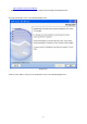
http://www.hp.com/go/rackandpower Note: This version of the software does not require manual setting of the file permissions. Read the introduction. Refer to the following diagram 2-2-6 Diagram2-2-6 Click the “Next” button, and choose the install folder. Refer to the following diagram 2-2-7.
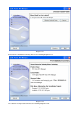
Diagram 2-2-7 Review the Pre-installation Summary. Refer to the following diagram 2-2-8: Diagram 2-2-8 The software is being installed.
Diagram 2-2-9 When the installation program is completed, click “Done”.
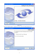
Click the “Done” button. If the software is installed successfully, the HP Value UPS Manager application can be found in the Start menu\Programs\HP Value UPS Manager folder. Refer to the following diagram 2-2-11. Diagram 2-2-11 For console mode environment: 1. Enter the directory according to the system and run setup.bin or setup_console.bin to start the installation program. 2. Read the information provided, and then presses ENTER to continue the installation. 3.
Diagram 2-3-3 9 Stop Agent: Right click the Tray Icon, and select the "Stop Agent" menu item. Refer to the following diagram 2-3-4 Diagram 2-3-4 9 Exit: For Windows vista and Windows 2008 OS, right click the HP Value UPS Manager Tray icon, and select Exit. Once you exit, you should restart the computer to start the HP Value UPS Manager application program automatically. But if you have administrator rights, you can start the application program again without restarting. There are two steps: 1.
4. Uninstall HP Value UPS Manager In Windows operating system There are two kinds of methods for uninstalling HP Value UPS Manager: 1. Click the “Uninstall HP Value UPS Manager” icon in “Start/Program/HP Value UPS Manager”. Refer to Diagram 2-4-1 below: Diagram 2-4-1 Notice: in Vista/Windows 2008, make sure you have administrator rights, and then right click and select “Run as administrator”. 2. Click “Control Panel/”Add/Remove Program”/Change/Remove(C)” button.
Diagram 2-4-3 Click the “Uninstall” button to begin to uninstalling HP Value UPS Manager.
Click the “Done” button. HP Value UPS Manager has been uninstalled completely. Refer to the following diagram 2-4-5 Diagram 2-4-5 In Linux system: Open the Terminal, enter the "/opt/ HP Value UPS Manager” directory and execute the command: .
Chapter 3 HP Value UPS Manager User Interface 1. "HP Value UPS Manager Monitor" window HP Value UPS Manager Monitor shows the "HP Value UPS Manager Monitor” window that displays a list of all Agents within the LAN. There is a tree view on the left side of the window that displays a hierarchical list of items, such as ‘Root’, ‘networks’, the Agents, the COM port, USB port and the UPS models. By clicking an item for UPS, the user can expand or collapse the associated list of sub items.
Diagram 3-1-2-1 The UPS status figure consists of five parts: AC, LINE, UPS, BATTERY, and LOAD. Each part is connected with a power cord. 2. Menu and Dialog 1) Auto Search Device When the user select the "Auto Search Device " menu item from "System" Menu, HP Value UPS Manager will start searching for the device connected to the computer’s serial or USB port. See the following diagram 3-2-1-1 and diagram 3-2-1-2. HP Value UPS Manager can monitor not more than four COM ports and one USB port in a PC.
Diagram 3-2-1-2 Click the item in the tree view, the user will see the information shown below: 1) All the computers running HP Value UPS Manager Agent on the LAN. 2) Device COM Port or USB Port. 3) The model type of the Device that is connecting with the related Agent. 4) The Current Status of the Agent which the user selects in the tree view.
Diagram 3-2-2 3) "Administrator Password Settings" Screen The “Administrator Password Settings” screen can be opened from the “Modify Administrator Password” menu item of “System” menu. Refer to the following diagram 3-2-3: Diagram 3-2-3 Only the Super User can set the Administrator password on the local machine. If you are not a super user yet, the "Administrator" screen will pop up first for you to log on as administrator.
Diagram 3-2-4 Users can select the check box “Delete” and click the "Delete" button to remove the selected events. Users can click the “Close” button to close the log. Users can click the "Purge All" button to delete all of the events. Note: If the “Delete” and "Purge All" buttons are in invalid conditions, which means your access right to the current Agent is “Read Only”, you can not carry out the operation. You may log in as super user through the “Act as Administrator” menu.
Diagram 3-2-5 Users can select the check box “Delete” and click the "Delete" button to remove the selected data log. Users can click the “Close” button to close the screen. Users can click the "Purge All" button to delete all of the data. Note: If the “Delete” and "Purge All" buttons are invalid conditions, which means your access right to the current Agent is “Read only” and you cannot carry out these operations. You may log in as super user through the “Act as Administrator” menu.
Diagram 3-2-6-2 Diagram 3-2-6-3 Click the “Settings” button of the event log in the “Record Setting” screen (Refer to the following diagram 3-2-6-4) to pop up the “Event Action” dialog. Refer to the following diagram 3-2-6-5.
Diagram 3-2-6-4 Diagram 3-2-6-5 The default value of the “Maximum file length” in the “Data Log Viewer” is 32KB (the maximum is 1MB). The default value of the record interval in the “Data Log Viewer” is 60 seconds (the maximum is 3600 seconds). Click the “View Log” button of data log in the “Record Setting” screen (refer to the following diagram 3-3-6-6) to pop up the “Data Log Viewer” screen (refer to the following diagram 3-2-6-7).
Diagram 3-2-6-6 Diagram 3-2-6-7 Note: Click the “Default” button and the parameters in this page will become the default. If the “OK” button is an invalid condition, which means your access right to the current Agent is “Read only” and you cannot setup the parameters, you may log in as a super user through the “Act as Administrator” menu. 7) " Device Control Parameters" Screen The “Device Control Parameters" screen will pop up when the user selects “Device Control Parameters" item from the “Device” menu.
Diagram 3-2-7-1 Note: "High limit of input frequency on bypass", "Low limit of input frequency on bypass", "High limit of input voltage on bypass" and "Low limit of input voltage on bypass" can only be set successfully when the UPS is in standby mode.
Work on bypass when UPS turned off - - - No Table 3-2-7-1 Note: If the “default” button is pressed, the parameters on this page will become the default values. For the HP T1000v UPS, the user can enable/disable the battery mode audible alarm though this dialog.
Diagram 3-2-8 Events are divided into three types of icons: Severity (red), Warning (yellow) and Message (blue). Note: to use the e-mail function, you must setup SMTP server. For detailed information please refer to “How to send event message by e-mail”. 9) "Shutdown Settings" Screen The “Shutdown settings” screen can be opened from the “Shutdown Parameter” menu item in the “Device” menu.
when utility power fails. Shutdown System __ __ __ No When this check box is selected, the system will be shutdown while the appointed UPS is being turn off. Suspend System __ __ __ No When this radio box is selected, System will be suspended to disk in shutdown sequence. This function only can be carry out in some Windows OS and hibernate support must be enabled from /Control Panel/Power Options/Hibernate.
down immediately while battery low the battery low event occurs, the Agent will shut down the UPS immediately, otherwise the shut down time will be controlled by the battery back up time. Shutdown remote Agents' Conditions __ __ __ __ The condition can be "UPS be shutdown" or "The time on battery exceed setting time”. Agents be Shutdown __ __ __ __ When the shutdown condition is satisfied, the Agent will send a shutdown signal to the appointed remote Agents.
Diagram 3-2-10 In the “UPS Self-Test Immediately” screen, users can select the type of self-test: Self-Test for 10 seconds, Self-Test until battery low, or Self-Test for XX minutes. The time range of self-test for XX minutes is from 1 to 99 minutes. Note: If the “OK” button is an invalid condition, which means that your access right to the current Agent is read only and you cannot carry out these operations, you may log in as a super user through the “Act as Administrator” menu.
denotes the Power On action, and the blue dot denotes the self test action. Click the “Add Test” button to setup the special time and monthly UPS self-test task in the popped up screen. The added self-test will be entered the schedule. If you select one of the UPS self-test tasks in the task list, you may modify the task that has been set in the popped up screen by clicking the “Modify” button.
Note: If the “OK”, “Add Test”, “Modify” and “Remove” buttons are invalid conditions, which means that your access right to the current Agent is read only and you cannot carry out setup, you may log in as a super user via the “Act as Administrator” menu. 13) "Schedule Viewer" Screen The “Schedule Viewer” screen can be opened from the “View Schedule” menu item on the “UPS” menu.
Diagram 3-2-14 The "Broadcast To" list box list the users. The user item must be selected to receive broadcast messages. You can add and delete user items by click the "Add" or "Remove" buttons (Note: the "All Users" and "Domain User" item can not be deleted). "All Users" means all computers in the LAN. "Domain User" means computers in the same domain with the local Agent. The "UPS message" list box lists the messages to be sent. You can select or unselect the message by clicking the message item.
Diagram 3-2-15 The email parameter settings are shown in the following Table 3-2-15: SMTP Server Name This is the mail server, which is used to send emails to the appointed users. Enter the IP address of the SMTP mail server here. For example, smtp.hp.com SMTP Account Name This is the account number for logging in to the server. Enter the complete address format here. For example, yyy@hp.com Password Input the SMTP account password.
The “UPS message” list box lists the messages to be sent. You can select or unselect the message by clicking the message item. All of the SMTP parameter default values are null, and can only be setup in the local Agent. To send an email to the appointed user, the SMTP server name or IPv4 / IPv6 addresses must be set, or the email will not be sent. Note: If you want to send email via Internet, you must have an SMTP account number on the Internet.
2. Receiver: The mobile phone numbers that can receive the SMS. It can be one or more. If the Event that you have selected occurs, the HP Value UPS Manager will send the short message to all the phone numbers in the "Receiver" list. 3. Send messages: A user can select the events that need to be informed by SMS.
Diagram 3-2-18-1 19) Temp You can make the interface show the centigrade or Fahrenheit temperature by selecting the submenu “Temp” of the menu “Preference”.
20) Date Format You can change the displayed date format by selecting the submenu “Date Format” of the menu “Preference”. The date is displayed with the format “Year/Month/Day”, “Month/Day/Year” or “Day/Month/Year”. See diagram 3-2-20-1: Diagram 3-2-20-1 21) Advance Settings You can change the font, size, color, and bottom image of the interface by selecting the submenu “Advance Settings” of the menu ”Preference”. The “Advance Settings” screen consists of “General” and “Bottom Image” views.
Diagram 3-2-21-1 Note: If you click the “Default” button, the parameters in this view will be turned into the default value. If the “OK” button is an invalid condition, which means that your access rights to the current Agent are read only and you cannot carry out the parameter setup, you may log in as a super user through the “Act as Administrator” menu. In the “Bottom Image” view: If you click the “None” box, the bottom image of the interface is “background color”.
Diagram 3-2-21-2 Note: By clicking the “Default” button, the parameters in this view become the default value. If the “OK” button is an invalid condition, which means that your access rights to the current Agent are Read Only and you cannot carry out the parameter setup, you may log in as a super user via “Act as Administrator” menu. 22) Language menu Users can select languages in the “Language” menu to make the interface display text in “Chinese (Traditional)”, “Chinese (Simplified)”, or “English”.
Diagram 3-2-22 23) "Communication Port Settings" Screen "Communication Port Settings" screen can be opened from the "COM Port setting" menu item of the "System" menu. For a Linux platform, the HP Value UPS Manager can't auto detect the Serial Port Devices. If the Serial Port of the system is not found in the default setting table, the user must add it manually in the "Communication Port Settings" screen before using it.
Chapter 4 HP Value UPS Manager Operation 1. How to convert the appointed COM port? When the PC with HP Value UPS Manager has multiple serial ports, the HP Value UPS Manager can allow the users to change the current connected serial ports of the Device via the “Auto search Device” menu. See the following Diagram 4-1-1: Diagram 4-1-1 The tree view on the left displays a hierarchical list of items, such as ‘Root’, ‘networks’, the Agents, the COM ports, and the Device models.
Diagram 4-1-2 When the user selects a device model, the "Manager" Window will show details about the device on the right. Note: When starting the Agent for the first time, it takes more time to communicate with the device. The software will keep a record of device information. Next time, HP Value UPS Manager will start according to the last record.
Domain user indicates that the message will be only sent to all PCs that are in the same NT domain with this PC. Special user indicates that the message will only be sent to one user or a group of defined users. To use this function, set up the “Add Broadcast User” screen first. See the following diagram 4-2-2: Diagram 4-2-2 After setting up the users who will receive messages, select the “OK” button to exit from the setup of special users.
Note: Only Server 2003 Ent/Windows XP platform can carry out the broadcast function. To receive broadcast messages, "Messenger Service" in Server 2003 Ent/Windows XP must be started. 3. How to use the schedule of Adding/Removing UPS self-test Open the “Battery Self-Test Schedule” menu from “Device” menu to popup the “UPS Test Manager” screen.
Diagram 4-3-2 In this screen users can make a choice in setting a UPS self-test task from the options of “once” or “monthly” in the combo box. You may set the start time of the UPS self-test in the date and time combo box. Note: the new self-test task cannot conflict with the UPS self-test task that has already been set and the task of UPS Power on/off. ¾ ¾ ¾ You can set the time span of self-test by selecting one of the buttons.
Diagram 4-3-3 Press the “OK” button to finish saving the setting. See the diagram 4-3-3. ¾ Modifying a UPS self-test task Select one of the UPS self-test tasks in the task list. Press the “Modify” button to modify the task that has been set in the popup screen. See the following diagram 4-3-4: Diagram 4-3-4 After the modification is finished, press the “OK” button to save the changes.
¾ Remove a UPS self-test task Select one of the UPS self-test tasks in the task list. Press the “Remove” button to cancel the task. See the following diagram 4-3-5: Diagram 4-3-5 4. How to use the schedule of Adding/Removing UPS on/off Open the “UPS OnOff Manager” menu from the “Control” menu to popup the “UPS OnOff Manager” screen.
Diagram 4-4-1 Note: It functions only for a UPS. If the “OK” button is an invalid condition, which indicates that your access right to the current Agent are “Read only” and you cannot set up, you may log in as a super user via “Act as Administrator” menu. ¾ Add the task of UPS OnOff Press the “Add UPS OnOff” button to popup “Off UPS” screen.
Diagram 4-4-2 In this screen, users can make a choice in setting the UPS Power OnOff option of “Once” or “Weekly” in the combo box. Set up the UPS off and restart time in the date and time combo box. Note: the new task of UPS OnOff cannot conflict with the UPS self-test and UPS OnOff tasks that have been set on the time. Press the “Cancel” button and the screen will be closed and the above settings are invalid.
Diagram 4-4-3 Press the “OK” button to finish saving the settings. ¾ Modify the task of UPS OnOff Select one of the UPS OnOff tasks in the task list, and then press the “Modify” button to modify the tasks that have been set up in the popped up screen. See the following diagram 4-4-4: Diagram 4-4-4 After the modification is complete, press the “OK” button to save the changes.
¾ Remove the UPS OnOff task Select one of the UPS OnOff tasks in the task list, and then press the “Remove” button to remove the task. See the following diagram 4-4-5: Diagram 4-4-5 5. How to use the network shutdown function It functions only for a UPS. Open the “Shutdown Parameter” menu item from the “Device” menu to popup “Shutdown Settings” screen.
Diagram 4-5-1 Remote Shutdown by Agent: Click the “Add” button in the” Shutdown Options”, and then enter the IP address of the agent in the pop up screen. Press the “OK” button to finish the setting. When the local Agent receives the specified agent's shutdown signal, the system can be shutdown in delay time. Shutdown Remote Agents: Click the “Add” button in the “Shutdown Remote Agents” screen, and then configure the conditions of shutdown. Enter the IP address of the agent in the pop up screen.
Diagram 4-6-1 Click the “Add” button in the” Shutdown Options” menu and then enter the IP address of agent in the pop up “Agents’ IP address” screen. The software supports both IPv4 and IPv6, and the user can input the address of IPv4 (for example: 192.168.5.106) or the address of IPv6 (for example: fe80:21b:b9ff:fe5b:5ad4). See the following diagram 4-6-2: Diagram 4-6-2 Click the “Add” button, and configure the Shutdown conditions in the pop up “Shutdown Remote Agents” screen.
Diagram 4-6-3 9 ¾ ¾ ¾ ¾ ¾ ¾ ¾ ¾ ¾ 9 ¾ ¾ 9 ¾ ¾ To setup the shutdown parameter: Shutdown options: Battery backup time: The time that the UPS battery is able to supply power when utility power fails. Begin Shutdown Immediately while Battery Low: When this check box is selected and a battery low event occurs, the Agent will shut down the UPS immediately, otherwise the shutting down time will be controlled by battery back up time.
7. How to modify the Device control parameter For the HP R3000v UPS: ¾ Open the “UPS control parameters” menu from the “Device” menu to pop up “UPS control parameters” screen.
Table 4-7-1 The following UPS control parameters can be modified: ¾ The limit value of the input frequency on bypass: when the frequency of the utility power is out of this range(2-10), the UPS will consider it abnormal and do not work on bypass. ¾ The limit value of the bypass voltage: when the UPS supplies power in bypass mode, if the utility voltage is out of this range(4-20), the UPS will turn off bypass output. ¾ The limit number of ERM setting is 0-4.
Click the “OK” button to save the changes. Press the “Cancel” button to make the modification invalid. Note: If the “OK” buttons is an invalid condition, which means that your access rights to the current Agent are read only and you cannot carry out the setup, you may log in as a super user via the “Act as Administrator” menu. 8.
Diagram 4-9-1 SMTP Server is the SMTP server address. The user can input either the IPv4 address (for example: 192.168.5.106) or the IPv6 address (for example: fe80:21b:b9ff:fe5b:5ad4); SMTP User is the account for logging in to the server. If the SMTP mail server needs password authentication, the user should input the password. Note: If the user uses IPv6 address, the IP must be included in “[]” when the user enters the SMTP sever address. Refer the below diagram 4-9-2.
Diagram 4-9-2 Setup the Receiver Email Address: Select the “Add” button from the “Email Settings” screen, and then the “Add Receiver Email Address” screen appears (Refer to the following diagram 4-9-3). Diagram 4-9-3 Enter the “Email Address” in the “Add Receiver Email Address” screen, then select the “OK” button to save and exit.
10. How to send event messages by mobile phone 9 Precondition The precondition of sending messages by mobile phone is that the computers with HP Value UPS Manager must have at least one communication port that is used to connect to a GSM Modem or a mobile phone.
phone numbers in the "Receiver" list. 3. Send message: The user can select the events that need to receive SMS. Finally select the “OK” button to save and exit. Another method to select an Event Code: Select one of the events (For example, AC Fail) from the “Event List”, which is on the left side of the “Event Action”, and then select “Send SMS” on the right side of the screen. Finally, select the “OK” button to save and exit. 11.
Diagram 4-11-2 ¾ Startup Monitor: Refer to the following diagram 4-11-3: Diagram 4-11-3 ¾ Select the Device you want to monitor You can select the Device from the tree view on the left side of the window. If the Remote Accept Control Permission Switch of the Agent is not on, you can only monitor but not control. The submenu “Act as Administrator” of the menu “System” is gray and cannot be selected. So if you do not log in as an administrator, you cannot control all of the operation.
Diagram 4-11-4 12. How to remotely control any device in a different network in LAN ¾ The computers being setup for HP Value UPS Manager must setup the TCP/IP protocol in the communication protocol. The ports that the software needs open by the firewall, refer to table 4-12-1 Port TCP/UDP 2198 UDP 2199 UDP 2200 UDP 2099 TCP Table 4-12-1 9 Steps for use ¾ Keep the communication normally: test with network command PING. ¾ Remote Control Permission Switch: This is a selectable menu item.
Diagram 4-12-1 ¾ Select the device you want to monitor Open the “Monitor Remote Device” menu item from the “Monitor” menu to pop up the “Monitor Remote Device” screen. The user can enter a computer name or IP address in the popup "Monitor Remote Device” screen. The user can input either the IPv4 address (for example: 192.168.5.106) or the IPv6 address (for example: fe80:21b:b9ff:fe5b:5ad4). Click on the “OK” button to finish the setting.
Diagram 4-12-4 If the Remote Control Permission switch of this Agent is not on, then you can only monitor but not control. If the Remote Control Permission Switch is on, then you can monitor and control this device. So after you login as a super user, you can control all of the operation. Refer to the following diagram 4-12-5. Diagram 4-12-5 13.
Port TCP/UDP 2198 UDP 2199 UDP 2200 UDP 2099 TCP Table 4-13-1 9 ¾ The computer being required to setup HP Value UPS Manager has been connected to the Internet. Steps for use ¾ Keep the communication normally: test with a network command PING ¾ Remote Control Permission Switch: This is a selectable menu item. The user can open the submenu “Accept Remote Device” of the menu “Monitor” in the HP Value UPS Manager on the computer whose IP address is 202.103.190.87.
The user can enter a computer name, IPv4 address or IPv6 address in the popup "Monitor Remote Device” screen. Click the “OK” button to finish the setting. Now you can find the device in the WAN, You can select the device from the tree view on the left side of the window. Refer to the following diagram 4-13-3. Diagram 4-13-3 If the Remote Control Permission switch of this Agent is not on, then you can only monitor but not control.
Appendix A—Glossary Explanation Agent—Agent is a background application of the Windows/Unix/Linux operating system. UPS Battery Low—When utility power fails and the battery supplies power, if the battery voltage is lower than a certain value (refer to UPS Specification), the UPS will send a audible alarm at 1 second intervals.
Shutdown Alarm Interval—after the shutdown warning begins (include time shutdown warning and AC fail shutdown warning), the interval of each warning.
Appendix B—HP Value UPS Manager Event Table Serial Number Event Description Type of Message Remarks Serious Can be set as no shutdown system through “Shutdown parameter” Serious Can set battery backup time through “Shutdown parameter” 1 UPS Battery Low 2 UPS Battery Time Exhaust 3 UPS Fail Serious 4 UPS Output Overload Serious Output load is more than 110% Warning The connection of communication cable is not good, or communication port fault.
26 Self-test cancel Information . 27 Self-test End Information . 28 Special date Self-test Start Information . Special date Self-test Cancel Information 29 . 30 Special date Self-test End Information . 31 Monthly Self-test Start Information . 32 Monthly Self-test Cancel Information . 33 Monthly Self-test End Information .
Diagram c-1-1 Please follow below steps to resolve the problems: Step 1, Get those support packages The user can get these packages from the installation CD, or where we provide, For 32bit, Deployment_Guide-zh-CN-5.1.0-11.noarch.rpm Deployment_Guide-zh-TW-5.1.0-11.noarch.rpm fonts-chinese-3.02-12.el5.noarch.rpm lv-4.51-8.1.i386.rpm stardict-2.4.5-5.i386.rpm For 64bit, Deployment_Guide-zh-CN-5.1.0-11.noarch.rpm Deployment_Guide-zh-TW-5.1.0-11.noarch.rpm fonts-chinese-3.02-12.el5.noarch.rpm lv-4.51-8.1.
a) Double click this rpm, and then click the Apply button. See the below diagram c-1-2-1 b) Diagram c-1-2-1 Ignore the warning message, and directly click the Install button.
c) Diagram c-1-2-2 If the install was successful, please click the Ok button.
Diagram c-1-2-3 Step 3, Reboot the operation system a) Check the result by System\...\Language function and the user can find the Chinese characters are shown normally. See the below diagram c-1-3-1: b) Diagram c-1-3-1 There is another way to check the result: run HP Value UPS Manager to check the result as shown below.
Diagram c-1-3-2 Step 4, install the packages via command line, a) Go to the directory where these packages are located. b) Use the command to install: rpm -ivh package-name. Use the package Deployment_Guide-zh-CN-5.1.0-11.noarch.rpm as an example, rpm -ivh Deployment_Guide-zh-CN-5.1.0-11.noarch. Additionally, please note the privilege problem, if there is no privilege to execute the package, you need assign privilege to it first, for example, use the command: chmod 777 Deployment_Guide-zh-CN-5.1.0-11.
Diagram c-1-4-1 2 Chinese Support Guideline for Windows XP English Version For Windows English version, if the Chinese support packages are not installed, the Chinese characters will be shown as similar grid characters.
Microsoft has provided the Multilingual User Interface Technology (MUI) to support the multiple languages problem. The user can refer to the following URL to get more information. http://www.microsoft.com/globaldev/drintl/faqs/muifaq.mspx#MUIques6 Please follow tag below steps to resolve this problem: Step 1, Get those support packages The user can get MUI packages via the follow two ways: a) Purchase MSDN from Microsoft. Microsoft will provide MSDN CD including MUI pack.
Diagram c-2-3 Step 4, Check the result, Run HP Value UPS Manager. Refer to diagram c-2-4. Diagram c-2-4 Or check the Regional and Language Options window. Refer to diagram c-2-5.
Diagram c-2-5