
UPS R12000 XR Models Maintenance and Service Guide

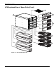

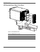
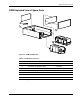
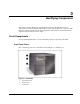
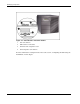
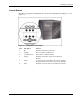
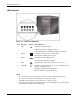
Table Of Contents
- HP UPS R12000 XR Models Maintenance and Service Guide
- Notice
- Contents
- About This Guide
- Chapter 1: Safety and Product Information
- Chapter 2: Illustrated Spare Parts List
- Chapter 3: Identifying Components
- Front Components
- Modes of Operation
- Rear Components
- Matching the Utility Voltage
- Module Locations
- Configuring the UPS Using the LCD Menu
- Chapter 4: Removal and Replacement Procedures
- Chapter 5: Troubleshooting
- Chapter 6: Specifications
- Index
HP UPS R12000 XR Models Maintenance and Service Guide 3-1
3
Identifying Components
This chapter provides illustrations and detailed descriptions of the UPS front and rear
components. Use the information in this chapter to locate and identify these components. This
UPS also contains an LCD menu for unit configuration. The functions on the LCD menu are
explained in detail at the end of the chapter.
Front Components
Use the following illustrations to locate and identify the front components of the UPS.
Front Panel Views
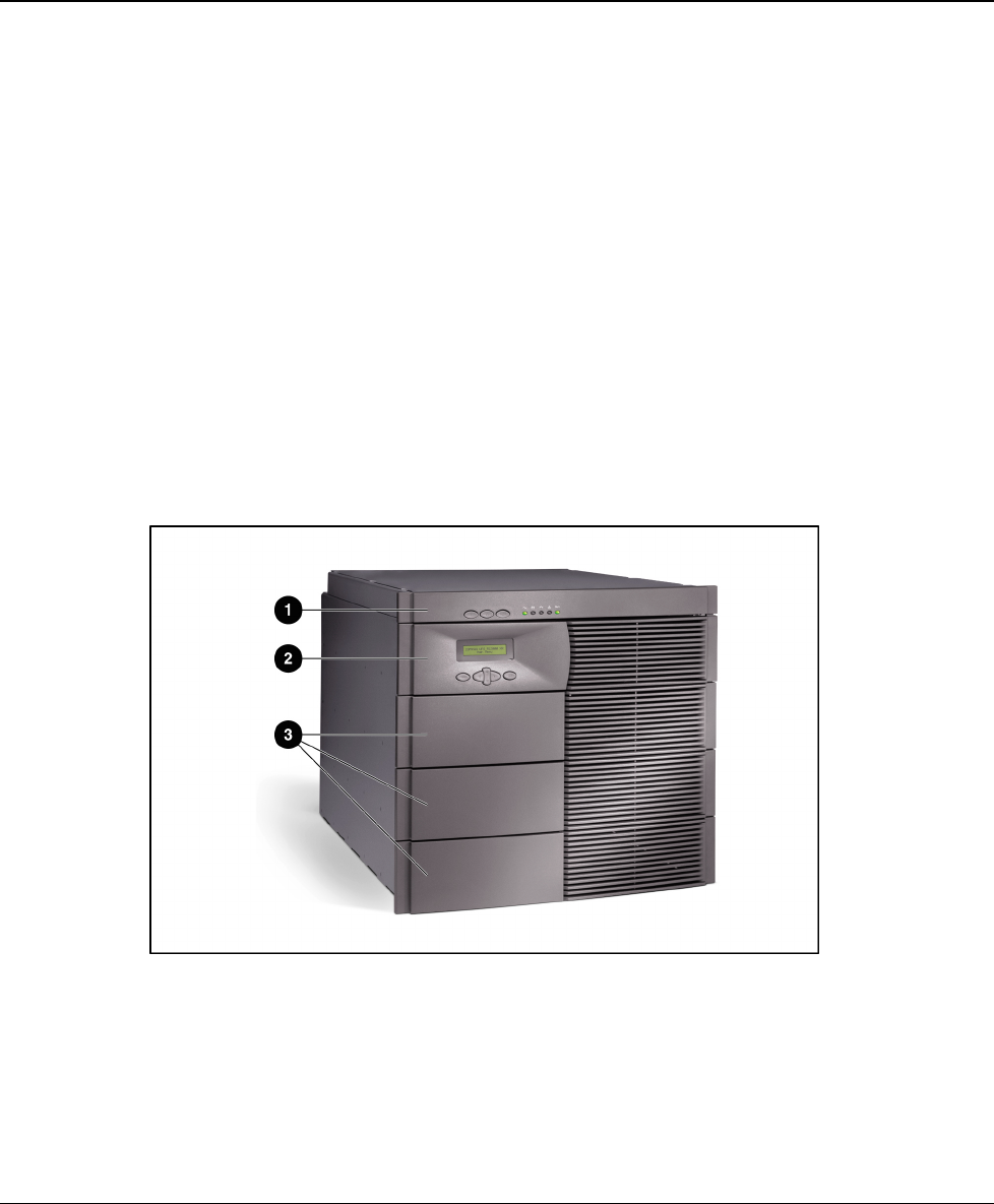
The overall front panel view of the UPS is shown in Figure 3-1 and Figure 3-2.
Figure 3-1: UPS bezels
1 Supervisory bezel
2 Control bezel
3 Front bezels