
UPS R12000 XR Models Maintenance and Service Guide

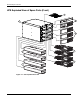

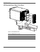
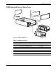
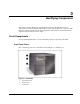
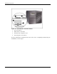
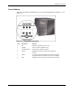
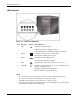
Table Of Contents
- HP UPS R12000 XR Models Maintenance and Service Guide
- Notice
- Contents
- About This Guide
- Chapter 1: Safety and Product Information
- Chapter 2: Illustrated Spare Parts List
- Chapter 3: Identifying Components
- Front Components
- Modes of Operation
- Rear Components
- Matching the Utility Voltage
- Module Locations
- Configuring the UPS Using the LCD Menu
- Chapter 4: Removal and Replacement Procedures
- Chapter 5: Troubleshooting
- Chapter 6: Specifications
- Index
Identifying Components
3-2 HP UPS R12000 XR Models Maintenance and Service Guide
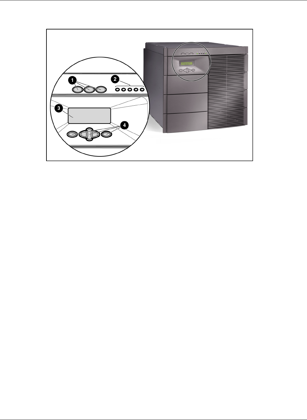
Figure 3-2: UPS indicators and control buttons
1 UPS control buttons
2 LED indicators of UPS status
3 LCD status and configuration screen
4 LCD configuration control buttons
For more information on using the LCD, refer to the section, “Configuring the UPS Using the
LCD Menu,” in this chapter.