
UPS R12000 XR Models Maintenance and Service Guide


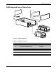
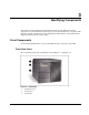
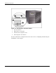
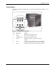
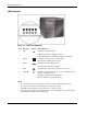
Table Of Contents
- HP UPS R12000 XR Models Maintenance and Service Guide
- Notice
- Contents
- About This Guide
- Chapter 1: Safety and Product Information
- Chapter 2: Illustrated Spare Parts List
- Chapter 3: Identifying Components
- Front Components
- Modes of Operation
- Rear Components
- Matching the Utility Voltage
- Module Locations
- Configuring the UPS Using the LCD Menu
- Chapter 4: Removal and Replacement Procedures
- Chapter 5: Troubleshooting
- Chapter 6: Specifications
- Index
Identifying Components
HP UPS R12000 XR Models Maintenance and Service Guide 3-3
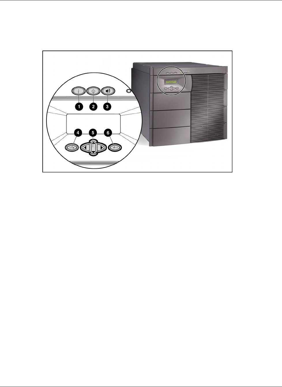
Control Buttons
The UPS control buttons and LED indicators are described and illustrated in Figure 3-3 and
Figure 3-4.
Figure 3-3: Front panel control buttons
Item Description Function
1 On Starts the UPS power-up of the load.
2 Standby Places the UPS in Standby mode.
3 Test/Alarm Reset Resets alarms or initiates self-tests.
4 Escape Navigates and deselects options in the LCD menu
structure.
5 Center Is a large four-way rocking button that controls navigation
through the LCD menu structure: up, down, left, and right.
6
Enter Navigates and selects options in the LCD menu structure.