
UPS R12000 XR Models Maintenance and Service Guide

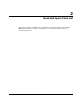
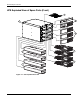

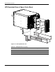
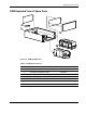
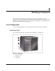
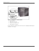
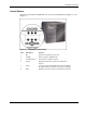
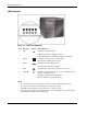
Table Of Contents
- HP UPS R12000 XR Models Maintenance and Service Guide
- Notice
- Contents
- About This Guide
- Chapter 1: Safety and Product Information
- Chapter 2: Illustrated Spare Parts List
- Chapter 3: Identifying Components
- Front Components
- Modes of Operation
- Rear Components
- Matching the Utility Voltage
- Module Locations
- Configuring the UPS Using the LCD Menu
- Chapter 4: Removal and Replacement Procedures
- Chapter 5: Troubleshooting
- Chapter 6: Specifications
- Index
Identifying Components
3-4 HP UPS R12000 XR Models Maintenance and Service Guide
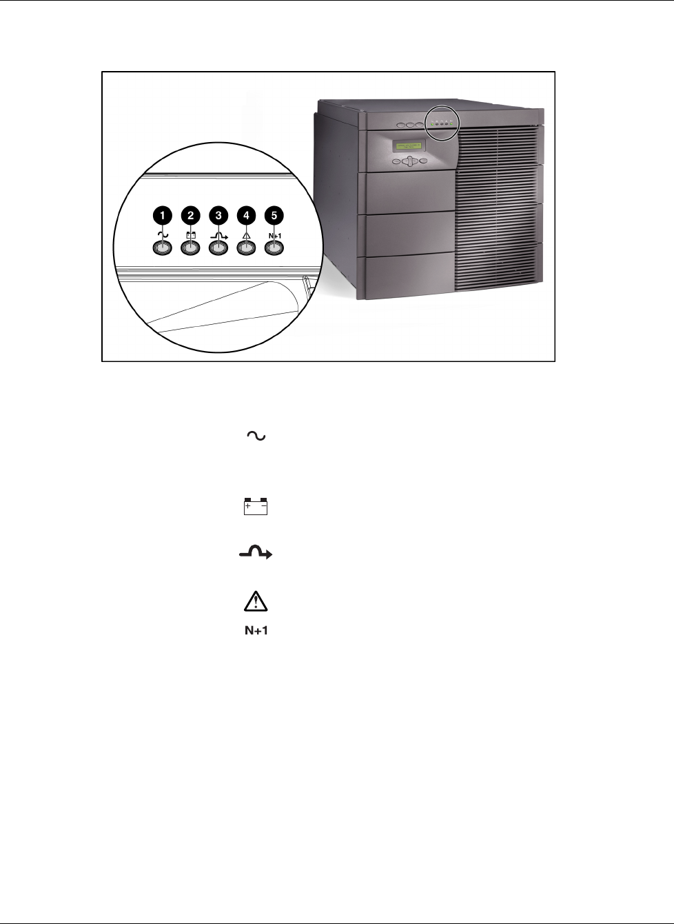
LED Indicators
Figure 3-4: Front panel LED display
Item
Description Symbol Meaning/Function
1 Utility
Solid GreenNormal operation
Rapidly Flashing Green—Startup in progress
Slowly Flashing Green Standby mode (batteries charging)
2 Battery
Solid AmberUPS is running on battery power
Flashing AmberBattery test in progress
3 Bypass
Solid AmberUPS is in Bypass mode
Flashing Amber—Bypass not available
4 Alarm
Solid RedOne or more alarms may be present or active
5 Redundant
Solid GreenRedundant mode (one or more redundant electronics
modules operating in system)
Flashing Green—Battery self-test initiated
OffNonredundant (not Redundant mode)
NOTE:
• Upon first powering up, the time required for the UPS to reach Standby mode ranges from
45 seconds to several minutes, depending on the battery state of charge.
• In Standby mode, the batteries charge and there is no output to the load.
• If no electronics modules are installed and utility is present, the LED lights cycle. In this situation,
the unit will be in either Bypass or Standby mode.