
UPS R12000 XR Models Maintenance and Service Guide
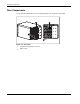
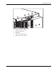
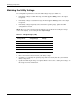
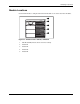
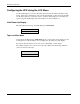
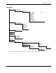
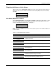
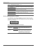
Table Of Contents
- HP UPS R12000 XR Models Maintenance and Service Guide
- Notice
- Contents
- About This Guide
- Chapter 1: Safety and Product Information
- Chapter 2: Illustrated Spare Parts List
- Chapter 3: Identifying Components
- Front Components
- Modes of Operation
- Rear Components
- Matching the Utility Voltage
- Module Locations
- Configuring the UPS Using the LCD Menu
- Chapter 4: Removal and Replacement Procedures
- Chapter 5: Troubleshooting
- Chapter 6: Specifications
- Index

Identifying Components
HP UPS R12000 XR Models Maintenance and Service Guide 3-5
Modes of Operation
The UPS has five modes of operation, indicated by the LEDs indicators (see Figure 3-4):
• Standby Mode
— When utility is present and output is off, the Utility LED (1) flashes slowly.
— Power is not available at the UPS output.
— The UPS monitors and charges batteries, if required.
• Operate Mode
— The Utility LED (1) is solid green.
— The UPS is supplying power to the loads.
— The UPS monitors and charges batteries, if required.
• Bypass Mode
— The Utility LED (1) and Battery LED (2) are off.
— The Bypass LED (3) is solid amber, and an audible alarm is active.
— The Alarm LED (4) is solid red.
— The utility is bypassing the unit and going directly to the load.
— The UPS monitors and charges batteries, if required.
• Battery Mode
— The Battery LED (2) is solid amber.
— The Alarm LED (4) is solid red.
— Utility power is not present.
— The UPS does not charge the batteries.
— Power is available at UPS outputs.
• Redundant Mode
— The Redundant LED (5) is solid green.
— At least one electronics module of the load can be in a redundant state (two or more
electronics modules working).
— All electronics modules share the load, but there is enough power to allow an
electronics module to go out of service.