
UPS R12000 XR Models Maintenance and Service Guide
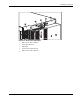
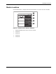
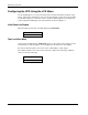
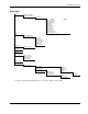
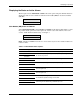
Table Of Contents
- HP UPS R12000 XR Models Maintenance and Service Guide
- Notice
- Contents
- About This Guide
- Chapter 1: Safety and Product Information
- Chapter 2: Illustrated Spare Parts List
- Chapter 3: Identifying Components
- Front Components
- Modes of Operation
- Rear Components
- Matching the Utility Voltage
- Module Locations
- Configuring the UPS Using the LCD Menu
- Chapter 4: Removal and Replacement Procedures
- Chapter 5: Troubleshooting
- Chapter 6: Specifications
- Index
Identifying Components
HP UPS R12000 XR Models Maintenance and Service Guide 3-9
Module Locations
Use the LCD menus to configure either the main module or one of the electronics modules.
1
2
3
4
5
Figure 3-7: UPS electronics modules, numbered
1 Main Module MM (includes all four electronics modules)
2 Module M1
3 Module M2
4 Module M3
5 Module M4