
UPS R12000 XR Models Maintenance and Service Guide
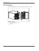
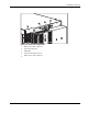
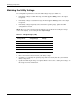
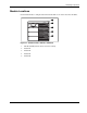
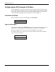
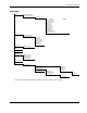
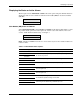
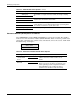
Table Of Contents
- HP UPS R12000 XR Models Maintenance and Service Guide
- Notice
- Contents
- About This Guide
- Chapter 1: Safety and Product Information
- Chapter 2: Illustrated Spare Parts List
- Chapter 3: Identifying Components
- Front Components
- Modes of Operation
- Rear Components
- Matching the Utility Voltage
- Module Locations
- Configuring the UPS Using the LCD Menu
- Chapter 4: Removal and Replacement Procedures
- Chapter 5: Troubleshooting
- Chapter 6: Specifications
- Index

Identifying Components
HP UPS R12000 XR Models Maintenance and Service Guide 3-11
Menu Map
Status
Main Module (MM)
Module (M) 1 through 4
Status/Alarms
Status
Alarms
Load Power Off
System Normal
Load Power On
On Battery
On Bypass
Manual Bypass
OverLoad
Autocalibrating
Starting Up
Module Failure
Unknown Stats xx
UPS Supporting Load
*
Meters
Main Module (MM)
Module (M) 1 through 4
Input Volts
Output Volts
Input Frequency
Output Frequency
Output Power
Battery Volts
Input Current
Battery Data
% Battery Charge
Set Time
Set Date
Firmware Vers
MM Control Vers
MM Comm Version
M1-M4 Versions
Display Module
Display Test
System Setup
Enter Password
Comm Setup
Set Voltage
Set HW Config
Serial Port 1
Serial Port 2
Set Language
Set Password
Opt-Slot 1
Opt-Slot 2
ERM Setup
Commission Batt
Parallel Mode
Baud Rate
For Capacity
N+1 Redundancy
* For a list of all possible alarm displays, refer to the section, “Alarms,” in this chapter.