
UPS R12000 XR Models Maintenance and Service Guide
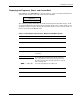
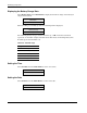
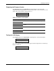
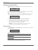
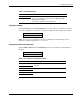
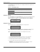
Table Of Contents
- HP UPS R12000 XR Models Maintenance and Service Guide
- Notice
- Contents
- About This Guide
- Chapter 1: Safety and Product Information
- Chapter 2: Illustrated Spare Parts List
- Chapter 3: Identifying Components
- Front Components
- Modes of Operation
- Rear Components
- Matching the Utility Voltage
- Module Locations
- Configuring the UPS Using the LCD Menu
- Chapter 4: Removal and Replacement Procedures
- Chapter 5: Troubleshooting
- Chapter 6: Specifications
- Index
Identifying Components
HP UPS R12000 XR Models Maintenance and Service Guide 3-19
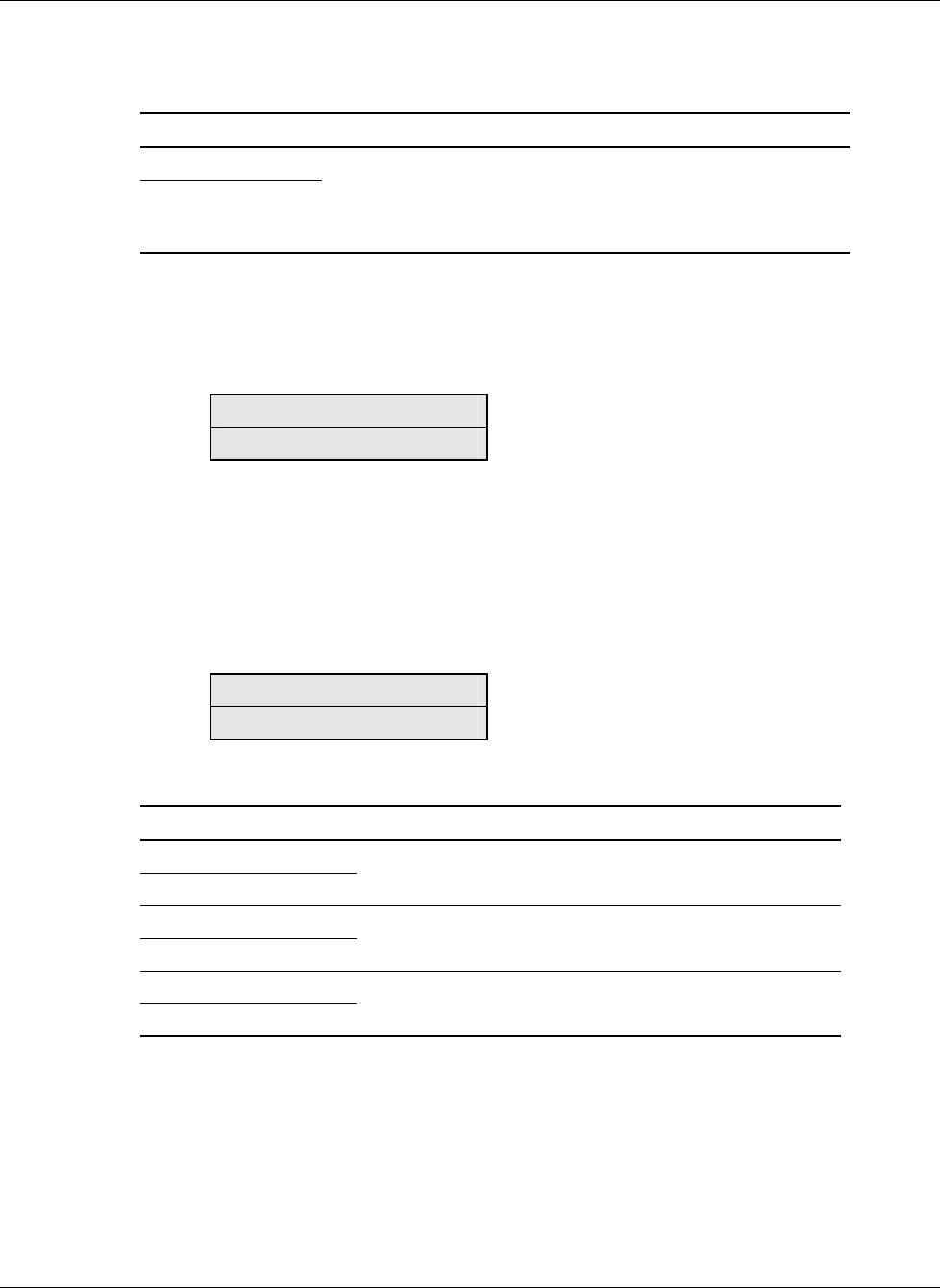
Table 3-9: Baud Rate Setup
LCD Display Explanation
Baud Rate
x
Choose the baud rate for the serial port or option slot selected.
Here, x is the baud rate and can be equal to 1200, 2400, 4800,
9600 (default), or 19200.
An asterisk (*) indicates the current baud rate.
Setting the Voltage
Select Set Voltage from the System Setup menu to set the voltage. An asterisk (*) indicates
the current configuration. The options for voltage are 200, 208, 220, 230 (default), and 240.
System Setup
Set Voltage
NOTE: This option is only available when the UPS is in Standby mode or Manual Bypass mode.
Otherwise, the LCD panel indicates
Not Available.
Setting the Hardware Configuration
Select Set HW Config from the System Setup menu to set the hardware configuration for
the UPS.
System Setup
Set HW Config
Table 3-10: Hardware Configuration Choices
LCD Display Explanation
Set HW Config
ERM Setup
Select this option to configure the number of ERMs
installed.
Set HW Config
Commission Battery
Select this option to enable a battery commissioning test.
Set HW Config
Parallel Mode
Select this option to go to the Parallel Mode menu options.